As a part of our MECH206 course; we were assigned to design and manufacture a walking robot, based on the design of Amanda Ghassei’s mechanism. Walking mechanisms possess several advantages over wheeled mechanisms, especially on non-smooth terrain. In the case of an obstacle on the way that cannot be avoided, a walking mechanism can step over the obstacle if it has a sufficient step height. Whereas a wheeled mechanism would probably be stuck or waste a high amount of energy while trying to roll its wheel over the obstacle. Amanda Ghassei’s robot is a fascinating example of such mechanism and we were lucky to analyze its design. During the design analysis, we focused on examining several traits of the mechanism which we think are important.
As stated previously, the step height is important for the robot to be able to walk on inconsistent terrains and the mechanism is therefore designed to maximize this trait. Stability is another aspect that needs to be considered, and the design of the Ghassei Linkage prevents it from being prone to falling over by keeping the vertical projection of the center of mass always inside its base of support. Lastly, there is not a need for a control mechanism since it won’t be operated by a computer or person via hydraulic system. The linkage is crank based which means the circular rotation of one point leads to the movement of another.
Meet Our Team
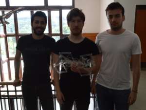
YAMAC GOKER
KAAN KAYA
METE AKYURT
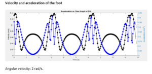
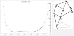
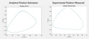
The foot of the mechanism is the part where the robot makes direct contact with the ground. The foot follows a cyclical path as the crank rotates. This path of movement is called the locus.
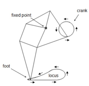
The locus of the foot which is shown in Fig. 1, can be divided into four parts. The support, lift, return and lower phases. Support phase is the term describing the motion where the foot keeps physical contact with the ground and the lift is the part where the foot moves towards its maximum height in the locus. The return phase occurs when the foot reaches its maximum height off the ground and moves in the same direction as the body of the mechanism. Finally, the lower phase describes the motion where the foot descends until it contacts the ground.
There are several crank based walking linkages such as the Theo Jansen mechanism and Hrones-Nelson four bar linkage. The Ghassei Linkage is an optimization of the Theo Jansen mechanism. An elaborate comparison between the Ghassei Linkage and Theo Jansen mechanism will be made in the following sections, however it is essential to understand the desirable traits of a walking robot.
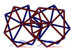
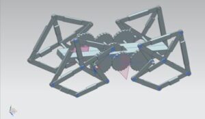
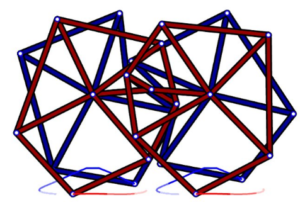
Our linkage has 4 legs and each leg contains 3 four-bar mechanisms,2 triangles and a crank. We used Siemens NX 11 to design our model. We started our model by sketching the foot of the mechanism. We searched the web for the animation of the mechanism and based our model on that. The links on the animation were too thin and it was a 2D model. In our model, we thickened our links for extra stability and for them to be able to withstand the weight of the structure. Since our model was going to be 3D, we had to put some extra parts on our links so that they do not intersect with each other. After completing the foot, we designed a base and a gear system. The base would be in the center and we were planning to put our motor on top of it. The gears did not intersect with each other properly in NX, so we had to export our design to SolidWorks. We fixed the gears and did the assembly in SolidWorks, finalizing the design process of our walking robot.
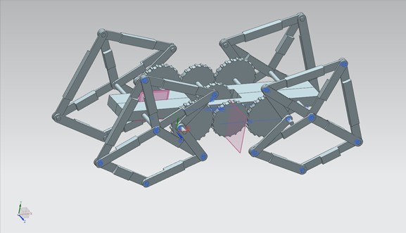
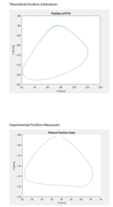
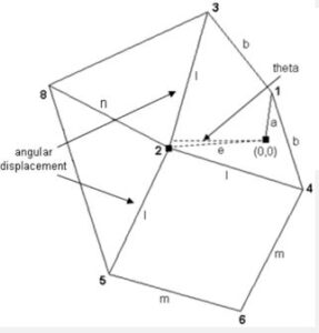
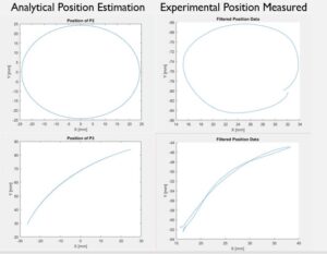
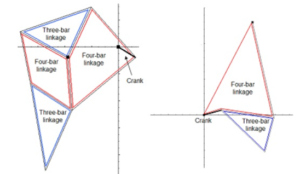
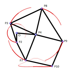
Ghassei mechanism consists of 2 four bar mechanisms with 2 fixed points, 1 four bar mechanism with 1 fixed point and 2 triangles. First, we found the positions of the four bar mechanisms with 2 fixed points. Positions of the triangles were changing according to the four-bar mechanism but their angles were always constant. Most difficult part was to find the position of the P10 because it was in a four-bar mechanism with only one fixed point. We found the position with the change of parallel angles and defined the position according to P7.
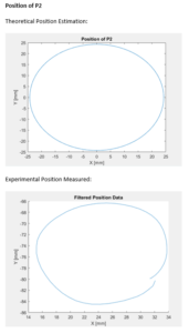
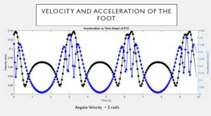
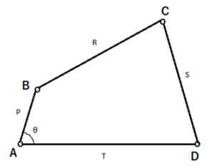
We used the four-bar linkage analysis in order to come up with our dynamic equations. We found the position vectors of all significant points in the system, took their first and second derivates to find also their velocity and acceleration with respect to the angle of the crank. An explanation of how to find the position vectors of significant points is shown below;
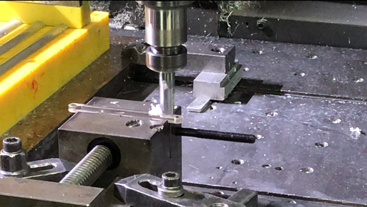
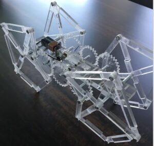
We corrected the gears on SolidWorks and our computer aided design was complete. The material we chose for our robot was plexiglass. It is a light material that would be convenient for the robot and we believed the transparency was giving it an aesthetic look. After that, a CNC (Computer Numerical Control) machine started on the process of manufacturing. A CNC machine is a computer programmed carving device. It reads a G code, where it obtains the required information about which cutting tool to select, how to move, which spindle speed or rotation rate to use. In Fig. 8, you can see the CNC machine that we used in our project. The machine cut the plexiglass and formed the links and the base for our mechanism. The machine then drilled holes on the indicated parts of the material for pin insertion and smoothened the rough edges of the links.