Neşe GÜLTEKİN
Umurcan YILMAZ
Flapping flight is a very efficient way to transport a unit of mass over a unit of distance, even though it requires extremely high power output. The wing flapping mechanism is a mechanism of flying animals (birds, bats etc.) and the basic idea behind it is the up and down motion of the wings. The main purpose of the flapping mechanism is to convert the rotary motion of the motor into the reciprocating motion of flapping wings.
The wing flapping mechanism can be used in areas where humans cannot involve directly or this mechanism can be used in vehicles where fixed or rotor wing fliers are not suited. Since this mechanism imitates nature, it has many advantages.
Wing flapping mechanism can be used in areas of: surveillance, defense applications, weather forecast, wildlife study and photography, crowd control, targeting and biochemical sensing.
The Mech 206 project we did, as Group 5, mimics this flapping of the wings by using a gear system that is connected to a power supply that drives the wing motion up and down through pinned connections.
Discussion
We obtained an average error rate of 80% for the velocity of the end of the wing, which was more than we expected. The reason for these errors could be our error while getting the experimental data. Using Maxtraq enabled us to get the experimental data easily, however it wasn’t perfectly precise, so some of the error can be caused by this program. Also, as we were measuring the experimental data, there were vibrations that we could observe visually, so that also contributed to the errors. However, the biggest cause of the errors were the non-alignment of our gears as we were taking the experimental data, therefore we could see from the position graph that we obtained for the experimental data that the end of the wing wasn’t doing an accurate displacement.
Another error we had was caused by the Matlab code. Our mechanism worked fine on Matlab, however one point in particular wasn’t exactly in sync with the rest of the flapping motion and had a 2% error. That contributed to our theoretical error rate.
Our acceleration errors were a lot more than the errors we obtained from the velocity calculations; the average error for the acceleration came out to be 176.5%. We can say that the reasons that caused the velocity errors apply to the acceleration errors.
Conclusion
For this project that we did called the ‘Wing flapping mechanism’ we analyzed, manufactured and experimented with a wing flapping mechanism. We expected to use the power of the motor to turn the gears and move the links that were connected to them, resembling a flying motion. We faced a few challenges with the manufacturing and with obtaining the experimental data and calculating the error, however in the end we managed to get all of them done and made the wing flapping mechanism work. The error rate came out a lot, which wasn’t very reasonable, however we could see where the errors were coming from and therefore we analyzed the problems.
Manufacturing
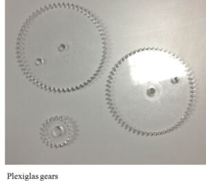
The manufacturing of this mechanism was done by first finding gears. At first we thought about getting the gears from outside and using aluminum for the material. However the problem was finding two identical gears and a smaller one that would drive them that would mesh perfectly and not be too heavy, so that we wouldn’t come across any problems with the end project. We did, indeed find two identical gears made of aluminum, however they were too thick, we had to shave them off to make them thinner and also they were both too heavy for our project. It was going to take a lot of time and be problematic; therefore we decided not to use those gears and instead decided to get them manufactured at school with Plexiglas. We drew the gears on Solid Works, because it was easier to get the profiles of the gears for manufacturing it than UGS, and in the end cut the gears in the Machine Shop in our school with the diameters 93 mm for the large gears and 33mm for the small gear. The thickness of the Plexiglas was 10 mm. Since the gears were made of Plexiglas and were light but durable enough, this enabled easy assembly.
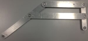
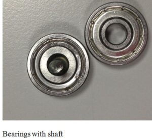
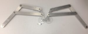
The next thing we did was finding the links and a motor. The links were originally going to also be manufactured at school using Plexiglas, however our dimensions were a little bit too big and it was also going to take a long time, since there was a queue of groups waiting to manufacture, we decided to buy the links from outside. We bought eight links in total along with 22 bearings with 19 mm outside diameter and 6 mm inside diameter. There were 19 mm diameter holes in either side of the links for the bearings to achieve tight fit. The links were made of aluminum and were a bit too heavy, but we managed to make the whole mechanism work regardless. We also bought a long aluminum cylinder with the diameter 6mm to cut into 20mm long pieces and use as shafts.
We needed a strong motor, so it that it would be able to carry the weight and enable movement of our aluminum links, because our original mechanism was going to be vertical. We bought our motor from Karaköy and it was a motor of a washing machine and was pretty strong. It was a DC motor with 24V and 698 rpm maximum.
We also got a board from outside to lay our mechanism on. We drilled holes in them with the same measurements of the diameters of the bearings for the fixed points and also connected the motor to the system with the help of a carpenter. However the bearings were falling off their holes because the aluminum links were too heavy and we couldn’t assemble the system completely.
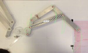
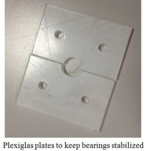
With the advice from our professor, we switched the mechanism from vertical to horizontal and got a bigger board with the measurements 100mm to 150 mm and also we used Plexiglas plates to hold the bearings in place with drilled holes in them with a diameter of 6mm for the shafts to go through. This enabled the bearings to stay in place as the mechanism worked.
Another problem we faced was the aluminum links touching the board, once we switched to the horizontal plane. For that problem, we cut a ping pong ball into two and glued each half to the ends of the wings, so as the wings went up and down, the balls enabled easy movement of the links.
Despite the problems, we finished the assembly process and tried if the mechanism was working with the motor and the rest of the elements of the mechanism. The wing flapping mechanism was working as we had envisioned it.