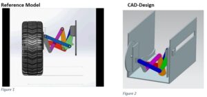
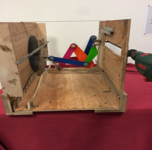
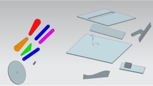
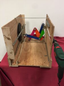
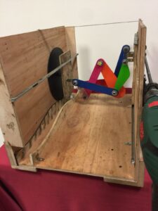
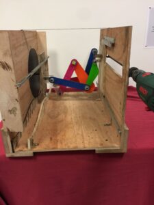
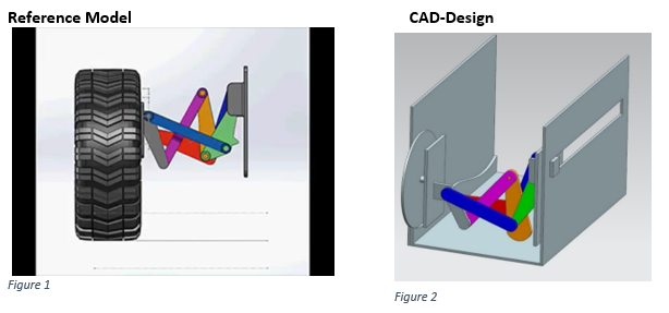
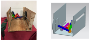
Our reference model includes 2 main parts and between them, it has six bars. Bars help the wheel go forward or back on the rough road. We first needed to learn the working principle of the suspension mechanism that we will produce. After learning the working principle, we determined the all position, velocity and acceleration equations that our bars have. Relating these equations we designed all parts on NX.11. After that, we determined to use which properties of motor we have to use this mechanism. For Matlab, we use our dynamic equation and found the theoretical data for position, velocity, and acceleration. Another essential thing is the material selection. Since the weight of the material could ruin the working principle of our mechanism and it would make it difficult for the system to work by increasing the friction in our mechanism, we gave much importance to weight in material selection. We thought that the most suitable material could be plexiglass, and as a result of this, we have produced plexiglass from our bars and wheels. The parts we covered like a box were designed in the shape of a wood because of the thickness of the parts. The thick parts were both too high in price, and the laser cutter at our school had difficulty producing parts of that thickness. After the assembly, we did experimental validation for the position, velocity, and acceleration for specific points which we chose before. Then we discussed the theoretical and experimental data.
Meet Our Team

BERKER HAMURSUZ
ONAT AKSARAY
BARISCAN GUMUS
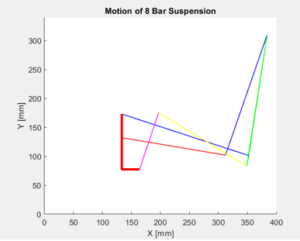
Our primary goal when designing our mechanism was to see a dynamic movement as we modeled it and to experimentally obtain the values we calculated theoretically. So we need to reduce the friction coefficient as much as possible, and we would have to use the motor’s power to move the mechanism. We first boxed around our mechanism to see our dynamic movement more clearly. This coating was a process to reduce the vibration that would otherwise occur while the motor was running. Later on, we preferred the screw shaft with 1.5 mm step number for the nuts as we wanted on the nut is going through to the screw shaft. The reason why we make the sine curve of the path simulation on our wheels is to show both that the suspension makes the wheels more comfortable in rough roads and also to provide a mathematical counterpoint to the rugged road that we will use when calculating the theoretical data. Every time we turn the threaded shaft with the drill, our nuts will advance by the number of steps, so our mechanism can move easily.
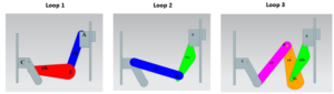
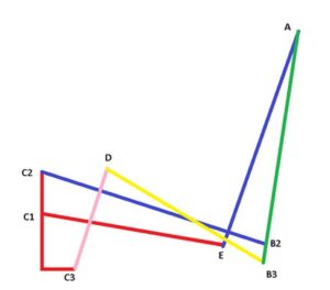
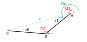
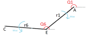
Before solving our dynamic equations, first we made research on four bar mechanisms. Than we applied four bar equations to our mechanism. Firstly, we divided our system in 3 loops.
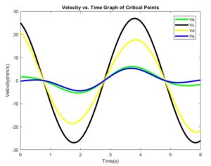
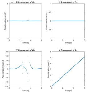
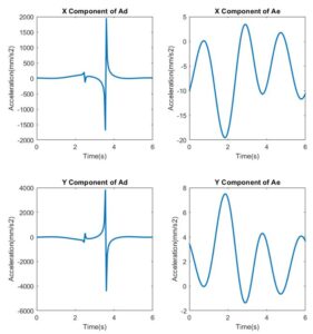
Since our mechanism travels on a sine wave, defined this function in MATLAB. The amplitude of this curve is 20mm and total path was 400mm considering the radius of the wheel. We measured the rotational screw shaft using a tachometer which is 2650 rpm. The screw pitch of our screw shaft is 1.5 mm. Considering these values the linear speed of the mechanism in Z direction happens to be 66mm/s. So the time it takes to complete path becomes approximately 6 seconds. Using the relation between the linear speed and Z position we defined the sine wave function for the wheel to travel on. X and Y coordinates of the points are determined by the position of the wheel on the sine wave. These are the basics of our MATLAB simulation and all the other analysis.