Necdet Kaan Karagülle
Batuhan Şengazi
An infusion pump is a device that regulates liquid pressure to induce fluid flow. In this project we used a cam mechanism to achieve this process. This mechanism consists of a series of cams that successively apply pressure on the tube in which the liquid would flow. The cams apply pressure on the tube via followers by converting rotational motion in to linear motion. The procedure we followed in the project started by studying several articles about cam mechanisms and accessing the information to come up with a design that would be suitable for our project. After this, we designed a cam mechanism with regard to the data we obtained.
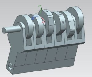
After the theoretical equations were derived, we used Siemens NX to design our cam mechanism.
Our design consisted of four parts:
Camshaft: The camshaft produced the required rotational motion that was to be converted to linear motion by the followers.
Block: The block was used to keep all the parts together while the infusion was in progress.
Followers: Followers converted the rotational motion into linear motion by dictating the radius of the part of the cam that was in contact with the follower.
Tube Container: The tube container contained the tube while the motion was in progress.
Manufacturing
Plexiglass was used to manufacture the block, camshaft and the tube container and the followers were made from steel. Dimensions of the design are available in the NX files.
The manufacturing process was as follows:
- The layers of the block were cut with laser, our block consisted of seven shaft holder layers and six follower guide layers. These layers were assembled using the plexiglass glue.
- The camshaft was integrated into the block by first placing the cams in position and guiding the shaft through the cams next. For angle stability, the cams were drilled from the cam surface through the shaft and steel screws were put in these holes.
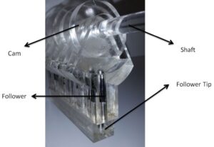
- Six followers were cut by a saw from a steel shaft and follower tips were placed at the ends of the followers that applied pressure on the tube.
- Followers were inserted into their holes from the bottom of the device
- The tube container was attached over the followers using super glue
- Power source was attached at the end of the shaft
- Compression sides of the cams were polished for ease of motion.