This project is aimed to simulate the design and creation of a singular auto shield wiper. The process of creation includes:
-
- Observation and understanding of a wiper mechanism
- Preparing a CAD design
- Calculations on working principles
- Creating a 2D MATLAB model and obtaining theoretical values out of it
- Creation of the solid parts from their CAD drawings
- Assembly of the parts
- Setting up an Arduino circuit and connecting it to the system
- Gathering experimental data via motion tracking and comparing it with the theory
Softwares used during the project are Siemens NX 11 for CAD drawings, MATLAB R2018a for the mathematical 2D simulation and Arduino for the circuit operations. Hardwares used are laser cutting mechanism for Plexiglass parts, basic circuit elements, a 9 rpm 12V DC motor, a 220-12V adapter and various tools as well as the raw materials.
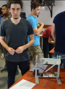
Meet Our Team
HALIL PERIT ERSU
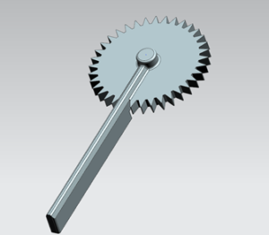
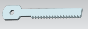
The mechanism that is commonly used in the auto shield wipers is rack and pinion mechanism. The project’s rack and pinion mechanism was a special design that uses rotational motion and turn it into a sinusoidal movement in a specific angle corridor. The rod that performs the sweeping motion which is called the wiper blade is attached to a gear which is the pinion of the mechanism that does a roughly 120 degrees of turn in every sweep. The velocity of the gear changes continuously throughout the motion making the blades slow down at the ends and traverse faster at the middle. This type of motion comes with two certain benefits:
- The motion will be smooth, so the parts will not face early degradation due to steep velocity changes.
- The wiper blades will not spend a lot of time at the middle of the swipe which could block the view through the window.
Therefore, understanding the dynamics of the system is an important criteria in order to obtain the desired motion type and to analyse it.
The motion is observed to be happening in 2 axes, X and Y in our case. Therefore all the calculations were made in X and Y axes considering how little Z axis interactions, like shear stress around the shafts, affects the system as a whole.
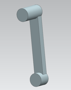
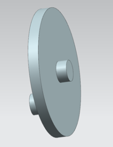
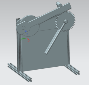
The main parts of the system are a disk that is connected to a power source from its centre, a rack, a gear that matches the rack teeth, the wiper blade, a holder pin, the base table and three shafts. Two of the shafts were connected to the motor disk and the last one is going through the centre of gear and connected to the holder. Horizontal alignment is chosen for the shaft connections to reduce the holder’s work and to prevent the rack from making and angle throughout the mechanism because of the gravitational forces.
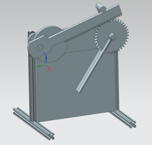
To create CAD models, Siemens NX 11.0 is used. Since most of the parts are to be 2D printed as plexiglass, edge blending and thickness changes did not included in the final draft. Important CAD modelled parts are:
Dynamic equations are derived from the relative axis equations of the Dynamics course.
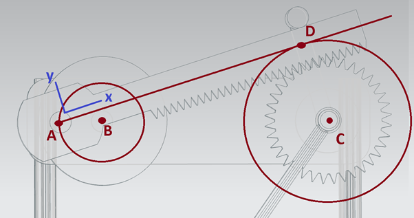
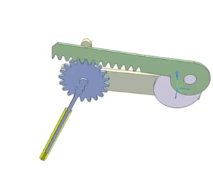
Point B is connected to the DC motor’s shaft and provide the rotational motion to the system via turning the disk. Point A is a stationary point that is revolving around the point B and connected to the rack. Point C marks the centre of the gear where the wiper blade is connected to it. Point D is the key point to analyse the system as well as the focus point in the dynamics calculations. It marks the point of intersection between the gear and the rack with an additional distance that is half of the rack’s Y axis thickness in order to calculate on the operating circle(which can be seen on the image) instead of the gear’s circumference.
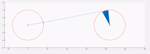
In this picture, the blue angle is the maximum angle that Point D moves along. When the point D is on the centre of the arc, wiper blade is at the leftmost or rightmost of its rotation depending on whether the rotation of point A is clockwise or counter-clockwise, when Point D is at the edges of the arc, the wiper goes along the center of its angle. The intersection angle for our project was 23 degrees which can be affected by gear’s radius, motor disk’s radius and the distance between points B and C. The wiping angle however is only a product of the such two radiuses’ ratio. For this project, it is calculated as follows:
[(2x40mm)/(πx60mm)] = 2.355 radians
This was the experimental wiper blade result which is used in the comparison since the Point D could not be tracked in a video because it is stationary on both the rack and the pinion.
For manufacturing, prepared sigma profiles and its connections and laser cut plexiglass are used. Some connections like the DC motor are done using bolts and screws and some plexiglass parts had joined together with plexiglass glue.
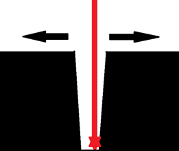
The precision of the laser cutter was not at the desired level and it caused the gear and the rack to differ from the original size. Since most of the cut the parts were 10mm thick, front dimensions and rear dimensions differed from each other. This representation shows how it happens on the cutter:
For manufacturing, prepared sigma profiles and its connections and laser cut plexiglass are used. Some connections like the DC motor are done using bolts and screws and some plexiglass parts had joined together with plexiglass glue.
The precision of the laser cutter was not at the desired level and it caused the gear and the rack to differ from the original size. Since most of the cut the parts were 10mm thick, front dimensions and rear dimensions differed from each other.
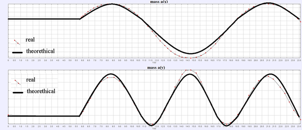
Motion Tracking is done to the wiper blade and its graph is compared with the expected graph of such a wave function. Since the wave functions’ derivatives are identical to it with π/2 angular difference, experimental validation is done onto the position graph of the wiper blade’s motion tracking:
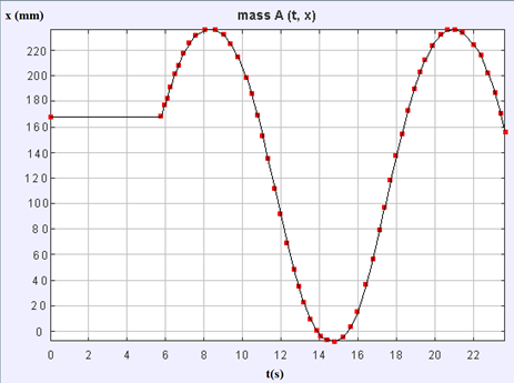
The Overlapping graphs of theoretical and experimental values of the wiper blades position is as follows which can be said quite as expected: