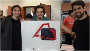
TEAM MEMBERS
Arda Şemsioğlu
Fikret Öğün
Rice transplanter arm is a mechanism making 2 dimensional motion that actuates from only one point that is attached to the motor The tip of the arm that picks up the seedling and plants it to the ground is analysed dynamically through the use of theoretical and experimental data in this project. Position, velocity and acceleration of the tip were the key points that were analysed and compared using the acknowledgements from dynamics class Mech206.
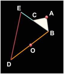
Although the planters used in the field today are all 4 bar mechanisms, the model used in this project is a 6 bar mechanism designed by Marc Plecnik. Since no literature review was found, all the calculations were done by the group members according to the following scheme (figure 1) designed according to the video our group was provided with. Points A and O are stationary and A is considered the origin (0,0) for all calculations. A is the point that is connected to the motor shaft which rotates 270 degrees clockwise and counterclockwise, actuating the motion of the arm. Point O is the point that bar BD slides on. Points B,C,D,E are points that link bars to each other with bearings, all are revolute joints. Point D is the tip of the arm, it is the point of interest for the analysis. Point D’s motion is analysed in three categories; position, velocity and acceleration.
CAD Design
CAD design was the first step of the project and the most necessary part for manufacturing. For the CAD design, the model in the video provided was used.The model in the video was a scale reference for the dimensioning of the links. Since no dimensional data was given, nor found in literary searches, all parts were drawn and dimensions were altered in order to get the correct motion in point D.
Bearings were used to let the links rotate freely. After the purchase of bearings, dimensions of the links where bearings were going to be tight-fitted were corrected according the inner and outer radiuses of the bearings. Another correction at the edges was needed because of the laser cutting process. The process burns the material causing differentiation in dimensions compared to the CAD design. In order for the end product’s dimensions to come up as desired, another alteration was done; 200 micrometers allowance was given.
Materials
-
- Plexiglass
- Bearings (8mm-12mm) and pins
- Wooden panel for display
- Coupling (7mm to 10mm)
- Strong Adhesive
- Spray Paint
Method
In order to manufacture the links, plexiglass was preferred due to the fact that it’s lightweight and available in the university. Plexiglass parts were manufactured by laser cutting. Models were imported from NX and converted to dxf format. All parts except link BD (the one with the gap) have a thickness of 5mm. The link that slides on the steel bar (BD) is 3mm thicker to bear the stress that is applied onto the inner surface of it during the motion. Plexiglass parts got colored to create a contrast so that the motion can bee seen more clearly. After that the assembly was done with the bearings, pins and the coupling using the equipment found in the machine workshop. The most challenging part of the manufacturing process was to make an appropriate coupling for the shaft. Since there wasn’t a suitable coupling with one end being 7mm and the other 10mm, a new one has been built in the machine shop. First, a plexiglass coupling was produced and assembled to the shaft with an adhesive, but the adhesive couldn’t bear the torsional stress and the coupling was broken. After the failure another one was manufactured from metal and fixed to shaft. Then it was decided that the setup will be supported vertically by a wooden plate that had a leg support so that while in motion, the panel won’t fall. The motor has been attached to the back side of the display for a clean look.
Motor Selection and Arduino
As the design made progress, it was decided to use a single motor to rotate the shaft. The shaft should perform a motion of 270 degrees in clockwise and counterclockwise, continuously. The required torque was calculated by multiplying the weight of the setup with the distance between the shaft and the gravitational point. Although the motion of the system was defined with angles, to get enough torque to lift the tip of the rocker arm against the gravity a DC motor was preferred instead of a servo. In order to rotate a DC motor in both directions it must be programmed by using a microprocessor. Arduino UNO was the main part to program the motor, but a driving shield should be inserted because of using a DC motor. Even though the motor, which was purchased, is a 12V and 60rpm, tuning the power supply to 10.35 V was sufficient to get the motion. In Figure 2 specifications of the motor can be found.