Clocks are the one of the oldest human invention. People used different types of devices to measure and keep the time such as sand clocks, water clocks, sun clocks and etc.. On the other hand, keeping the accuracy of the clocks was the main problem for clocks. Mechanical clocks had started to be standard timekeeping devices at the beginning of the 14th century. With invention of the mainsprings, clocks became portable devices. After pendulum clock was invented in 1656, pendulum clocks would be the most accurate timekeeping devices until the quartz oscillators’ invention in 1930s. Although, quartz clocks are the most common timekeeping devices, mechanical clocks doesn’t lose their popularity. Mechanical clocks are still sold for million dollars.
Main concern about the clocks is keeping time accurately. Quartz clocks are really precise timekeepers that’s why they are the most common timekeepers. On the other hand, keeping accurate time with mechanical clocks are hard thing to do, and, it was the main concern of this project too. Therefore, this project had been conducted in wide research background.

Meet Our Team


ANIL AKSEKI
MUHAMMED LATIF SATIR
SERHAN ENES KALMIS
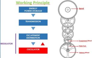
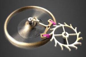
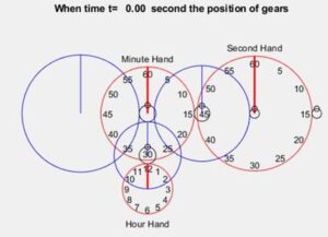
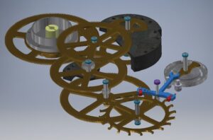
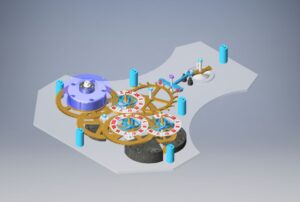
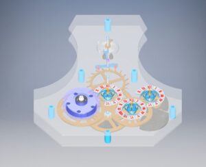
Mechanical clocks are basically made of gears, balance wheel-hairspring and mainspring. Mainspring provides energy to mechanism and this energy is transferred to hairspring. Hairspring oscillate with a certain period and regulates the whole systems period. While its oscillation, gears rotate according to systems period and clock is demonstrated via these gears depending on the ratio of these gears. Working principle of the mechanical clocks is as shown below.
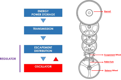
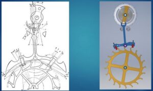
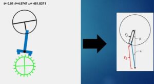
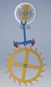
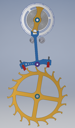
The most critical part of the project is escapement part. Because, whole mechanism is regulated with this part. Escapement wheel rotates with the energy that is provided by mainspring. Energy is transferred to balance wheel with escapement wheels push to pallet fork. With this energy, balance wheel starts to oscillate with a certain frequency. This frequency depends on design parameters of the balance wheel and hairspring. In every oscillation, pallet fork bangs to banging pins two times. While pallet fork moves one banging pin side to another, it release the escapement wheel. In this time interval, escapement wheel and rest of the gears released.
Design of the project was based on small scale mechanical clocks. Design parameters were determined by using small scale mechanical clocks formula were used due to lack of bigger scale mechanical clock sources.
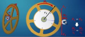
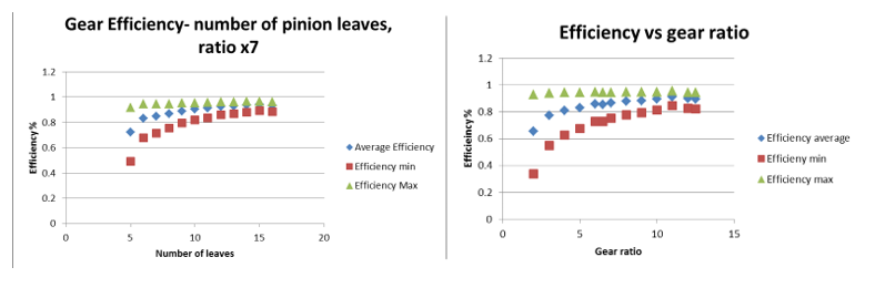
Design of this project was too complicated. So that, a lot of sources were used in order to find which design would be more efficient and more reliable. Every detail of the design and technical change could make very big problems. For example, gear ratio and types of gears were really important. Sources shows that higher gear ratio and higher number of pinions makes more efficient design. Gear ratio issue will be explained further parts of the report, but, it can be said that 1 rotation of the mainspring’s gear means 28800 rotation of the escapement wheel. This is the gear ratio between two endpoint of the mechanism. Graphs about the gear ratio efficiency is shown below.
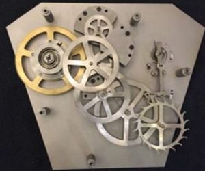
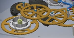
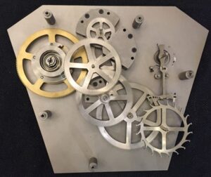
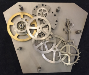
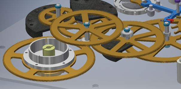
There are four shafts with gear and pinion. Locating them with an exact position in minimal size was hard thing to do. Also, gears should fit between two plate for stabilizing the gears. That’s why middle plates were used for some gears stabilization.
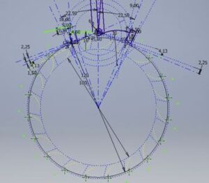
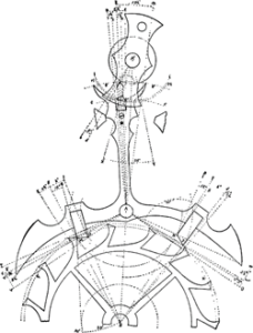
The most complex part of the system was escapement mechanism. Rest of the system were designed based on parameters of the escapement mechanism. Escapement mechanism were designed for 4 Hertz frequencies. It means the pallet fork of the mechanism makes 8 beat for a second for accurate time keeping. Escapement wheel is released by the pallet fork one time for each cycle of the balance wheel. Also, escapement wheel has 20 teeth. That is, escapement wheel makes full rotation in 5 second.
For escapement mechanism, Swiss Escapement Mechanism was used as the reference. This escapement mechanism gives more reliable time keeping accuracy due to geometries confidence. Also, this types of mechanism have more resistance to fatigue due to curvature shapes of the teeth. To get long life clock, system should be resistant to fatigue, because, system work regularly.
CAD model creation was started with modelling of the gears. Gears were designed by using cycloidal gear models on the internet and applied to mechanism with 0.75 module and based on teeth numbers. Then, gears were located by considering the reference diameters of gears. To satisfy proper ratio between gears, pinions were used. Difficulty of modelling the gears were positioning the gears. Distance of gears to each other was known from calculations, on the other hand, number of gears and diameter of gears affect the positioning. So that, some of the gears were attached with middle plates as stated before. Also, for mainspring position, receptacle was designed onto the mainsprings’ gear.
Manufacturing this complex system with small tolerances was really critical. Because, time accuracy of the clock depended on every detail. For example, hairspring was designed in millimeter scale. Tolerances of millimeters were in terms of mikrons. Also, positions of the gears were really critical too. If the gears axis through the shafts slid, gears may stuck and energy of the mainspring cannot be transferred as wished.
The most critical parts of the mechanism are springs as stated before. That is, critical dynamic equations were spring equations. There are plenty of source in order to calculate the spring constants and spring designs. So that, spring patents and mechanical clock books were checked to find the correct formula. All sources include watch base spring formulas and this small scale formulas were applied to bigger scale.
Firstly, the moment that mainspring applied to its base gear was directly proportional to width, number of winding, cube of the thickness and modulus of elasticity of the spring, on the other hand, inversely proportional to length of the spring. Structural steel was used as mainspring material.
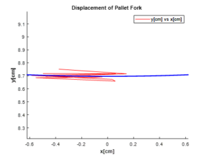
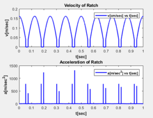
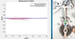
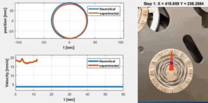
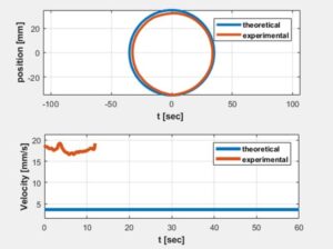
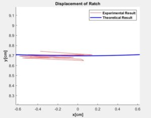
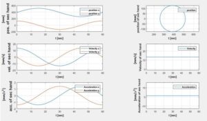
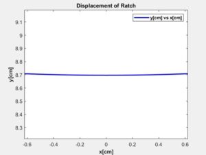
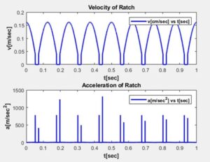
Hairspring’s design parameters were entered and simulated for expected movement of the balance wheel. By the hairspring moves, pallet fork was released and holded consecutively. Interval angles for pallet forks releasing defined with ‘If’ case under timing ‘for’ loop. Designed values of pallet fork was an important parameter for velocity and displacement analysis that derived from MATLAB. Since the expected frequency of the system was 4 Hertz, balance wheel cycling with 4 Hertz in the simulation.
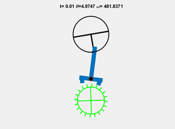
As stated, mechanism works with 4 Hertz. Due to speed of the mechanism, it was hard to make analysis with video tracking. By considering MATLAB can give 20 FPS in best situation, it was not compatible way for tracking 4 Hertz mechanism. In video tracking, head of the pallet fork was tracked. Corresponding pixel for 1 mm was arranged in the tracking code and then expected path of the pallet fork and tracked path were put on each other. Since the orientation of the hairspring, pallet didn’t bang to left banging pin side. But, tracked path shows the expected positioning data. Pallet fork couldn’t reach one side and finished its rotation before the left banging pin.