TEAM MEMBERS
Güçlü Yardımcı
Umut Can Çakmak
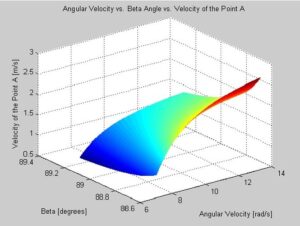
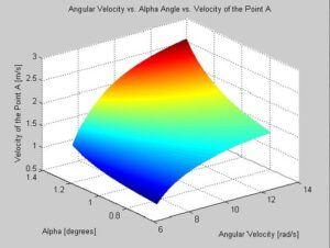
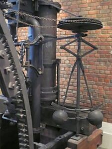
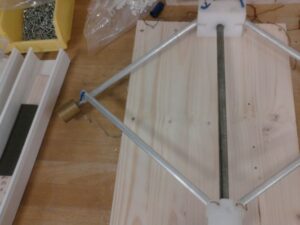
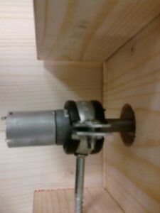
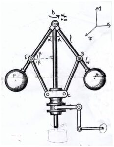
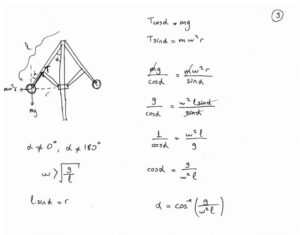
Our device is mainly composed of an engine, a centrifugal governor, two rods, and a slider. The governor, mainly used for regulating the speed of a machine, will be used to move the slider in our project. Briefly looking the history of the governor, we can see that it was primitively used in windmills from 17th century onwards. However, the governor as we know (and have built) is from the designs of famous James Watt. He patented the design in 1788. Among other improvements, he and his partner Boulton enhanced the present Newcomen engine system and produced a steam engine which was up to five times as efficient as the Newcomen system. The governor is supposed to regulate the fuel flow to the engine, again, through its connection to the engine. As the masses of the governor expand due to the speed of the engine, fuel flow is blocked thus the over-speeding is prevented. Mainly used in steam engines in the early stages of the industrialization era, the governors are nowadays can be found usually in the museums. Working principle of our governor is a DC engine spins the disk beneath the masses, that disk is connected to the governor’s main rod and spins the whole governor. By centrifugal force, masses move upwards and the slider on the upper part of the arms moves downwards. This leads to an up and down movement on the first connecting rod which leads to a transitional and rotational movement on the second connecting rod and finally a horizontal movement on the slider.
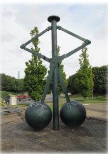
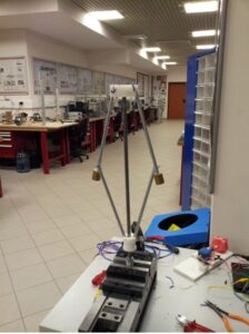
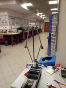
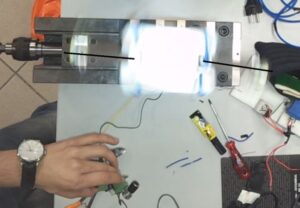
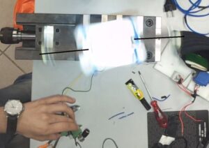
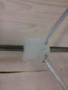
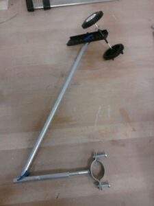
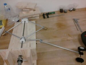
As mentioned before, our system is composed of an engine, a governor, three connecting rods and a wheel couple. The most difficult part was to assemble the governor. First of all, there was a main rod that governor’s masses and arms are connected. After that, we handled the upper part of the arms and the masses of the governor and connected them to the top of the governor. Then, we assembled the lower parts of the arms to the sliding part which slides on the main rod and regulates the motion of one connecting rod. We have the following final device in Fig. X. Lastly, we placed a DC engine at the bottom of the main rod. After that we connected the three connecting rods to the sliding part with a shape of ‘Z’ letter. At the other side of the connecting rods, there is our wheel couple which we use as a slider.
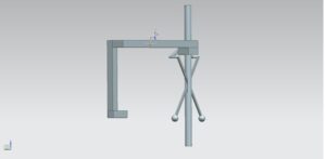
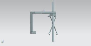
This is our first governor design in UG NX. It is more like a draft of our model. We decided not to use this model because the rods pass through the main rod, and there is not enough space for them to move. Thus, this type of a building can easily be broken.