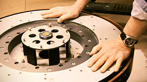
Expendable Table, named as Capstan-Fletcher Table, was first made by Robert Jupe. He developed the table in the nineteenth century. The patent of the table was taken in the year of 1835 by the Jupe himself. The table he built was round at first and had a practical design. Just like the table’s usage today, the lower parts elevate as the user turns the table connected to the parts similar to ones in the Figure 1 however, the leaves couldn’t be hidden underneath the table and the user had to place them manually. Addition to that the table’s process of opening was very slow and the round shape wasn’t perfectly fit.
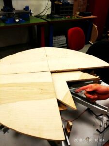
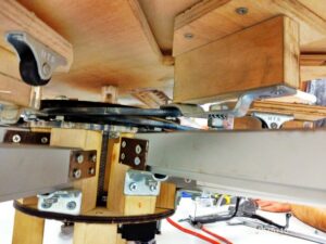
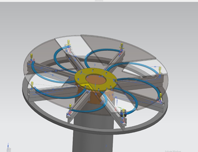
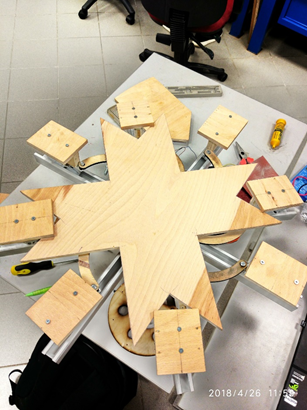
Today, the tables are manufactured by David Fletcher himself as he gave his name to the product. He improved the table constantly and created a durable product. A modern expendable table consist of approximately 5,000 odd separate parts. The superb advantage of the Capsten-Fletcher Table is the table’s ability to double the seating capacity while conserving the circular shape. This expansion process can be also done electronically. In the commercial design of David Fletcher, the table has an aluminum honeycomb in the center. The honeycomb gives the table the desired lightness and rigidity when the other parts are applied. In Figure 2, the honeycomb is shown. The table completes the radial expansion by only rotating 120 degrees. 4 grand parts are positioned at the top of the table while the small 4 are positioned beneath them. On the bottom surface of the table lies the middle part. The middle part can take many shapes. Most of the tables manufactured for commercial purposes have star shaped middle parts however, this can vary like any other variable in the project.
Meet Our Team

BERKEY KULLUKCU
BERKE ATASEVEN
TANIL ORHAN
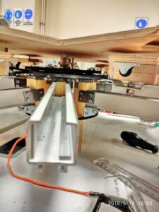
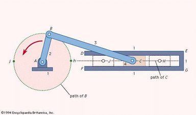
Slider-crank mechanism is used to convert linear motion to rotary motion similar to reciprocating engines or to convert rotary motion to linear motion just a reciprocating piston pump [2]. The mechanism benefits from a profile to create the linear motion. In real world applications, part 1 in Figure 3 act as a fixed frame. The frame has a cylinder inside which moves back and forth as denoted in part 4. The bearing of the crank is labeled with “A”. The rod at part 2 connects part 1 and part 3 together. All parts labeled with letters have bearings attached. With the help of the bearings, the system can easily rotate and makes a continuous motion. Gasoline engines uses slider-crank mechanisms. In an engine, in phead of the piston would be at EG point and the explosion would cause the piston to move towards the center. To return back to the original state, the system must make a rotation and fulfil the purpose of being a slider-crank mechanism. In the expendable table, the slider parts work as fixed frames. The carts go back and forward inside the sliders in order to displace the leaves and widen the table. The main gear at the middle of the table makes a rotary motion as a consequence of these progresses.
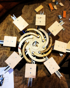
CAD design was done with Siemens NX. Features such as extrude, pattern, hole and revolve are used in the design. Design had more than 130 parts. The number grew higher when the nuts and bolts are added. The assembly was also done in Nx. In Figure 4, one can see the assembly process of the table. Furthermore, using the motion feature, the movement of the parts are predicted beforehand. The motion video of the table was also created.
Any information about the table couldn’t from different sources therefore, dimensions of the table are taken proportional to each other. Many of the dimensions are changed in the manufacturing phase.
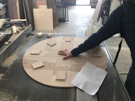
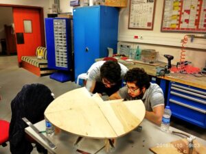
Most of the parts were made from wood in the project. Wood was easy to obtain. The carpenter’s shop in the university had spare wood. Those woods are used free of charge. Furthermore, the cutting process of the wooden parts were made in the workshop. Parts were given shape with the electric saws. The carpenters used 2D drawings of the parts and dimensions on them to create the parts. Most of the parts were created in the carpenter’s shop as in Figure 6. Some parts weren’t cut precisely therefore, additional visits were made. On the other hand, using wooden parts in the project had different disadvantages. Firstly, thick wood couldn’t be cut with the laser cutting machine easily. Laser cutting was applied to the wooden parts consecutively to take effect. Certain parts couldn’t have hollowed from the wood even after the laser cutting therefore, these parts are curved with a knife. Furthermore, wood didn’t have enough resilience to support the slider parts in the project and fractured in many occasions such as screwing.
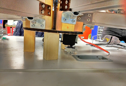
Cutting holes in the parts was the most time-consuming process. Drill machine was used in many occasions. In some sections, milling is used to create bigger holes in radius. Turning machine was also used to shorten the steel and plexiglass rods. The middle part is intended to be elevated with the help of a step motor.Step motor was able to create torc however, speed was a deficit. Consequently, a servo motor was used. The motor had 11 kgcm torc which was sufficient. The elevation speed of the middle part was still a deficit after the installation of the servo. 60 seconds took the middle part to elevate upward with a step motor. A 3-cm-diameter pulley was glued on the top of the servo motor and connected to a 1-cm-diameter pulley with a belt. With that, the elevation process reduced to 5 seconds.
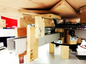
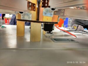
The table has 95 cm diameter when fully opened. 4 large and 4 small parts creates the upper layer when the middle part sits on the proper place. Large parts have 37.8 cm length whereas small parts have 28.4 cm from top to bottom. Middle part has 52.3 cm in length. Small parts elevate about 2 cm when the table is fully opened. Carts make linear motion in slider parts which are 25 cm in length. Carts assembled to small parts have specific parts which are manufactured from plexiglass. Inside these carts, tire assembled wooden parts climb along the ramps which are pasted to the end of the sliders.
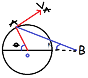
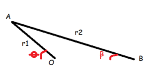
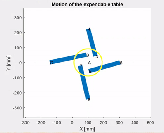
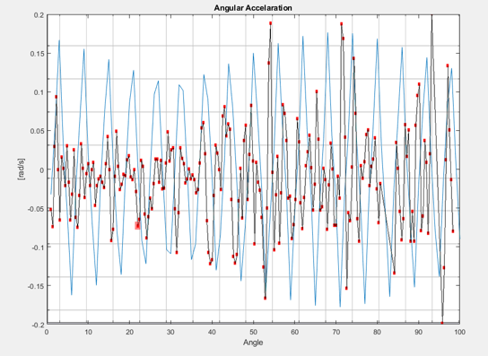
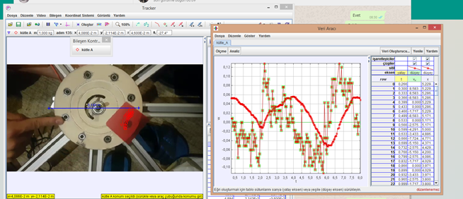
Points on the main gear are labeled as A,O and B as one can see in Figure. Using the equations, angular accelerations, angular velocities, accelerations and velocities of the points founded.