Deniz Çağatay
Yunus Emre Yavuz
Selin Aksoy
İpek Nil Şamcı
Atalay Kemal Demironaran
Introduction:
Our project is a four-stroke gasoline engine. Since this is an introductory course in mechanical engineering design, we thought that an engine would be a good fit as it is one of the cornerstone machines in mechanics.
An engine is a machine that converts energy from a fuel to some mechanical energy, creating motion in the process. Therefore, a motorcycle engine is an engine that powers a motorcycle.
How a 4-stroke gasoline engine operates:
The intake valve opens during the intake (first) stroke to allow fresh air from the atmosphere into the engine cylinder. The motion of the intake valve is controlled by a camshaft. The exhaust valve remains closed during the intake stroke. The downward motion of the piston creates partial vacuum inside the cylinder, pulling the air molecules inside. The intake stroke ends with the intake valve closing.
The air encompassed in the cylinder during the intake stroke is compressed with ratios ranging from 12:1 to 22:1 during the compression (second) stroke. The pressure and temperature of the air (inside) is raised. Both valves remain closed isolating the combustion chamber. This stroke ends with the fuel injector, injecting a finely atomized form of gasoline into the combustion chamber.
compression raises the pressure and temperature of air to match the self-ignition temperature of gasoline during the power stroke (third). The fuel molecules absorb the heat from the air and vaporize. This results in combustion and the subsequent generation of energy. The trust produced due to the combustion of fuel pushes the piston down.
Combustion of fuel produces exhaust residue gasses composed of unburnt fuel particles and harmful pollutants like CO2, NOX, SOX, etc. During the exhaust stroke (fourth) the exhaust valve opens and allows the disposal of the exhaust gasses into the exhaust port and further down the exhaust system.
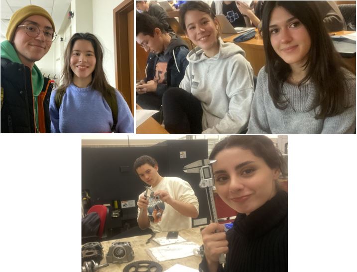
Disassembly:
We measured almost all of our dimensions using the digital 150 mm digital caliper we purchased. We decided to purchase a brand new one to minimize measurement errors due to calibration..
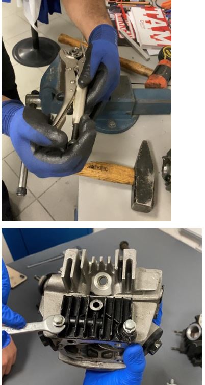
The engine arrived with most of the larger pieces (e.g. the individual cylinders) disassembled. Majority of the remaining pieces could be disassembled using different sized screwdrivers and ratchets provided in university lathe. However, we had to use a mallet to remove certain pieces such as bullbearings which were tightly bound using heat.
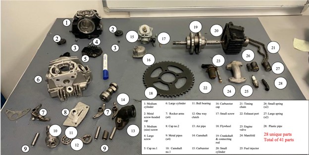
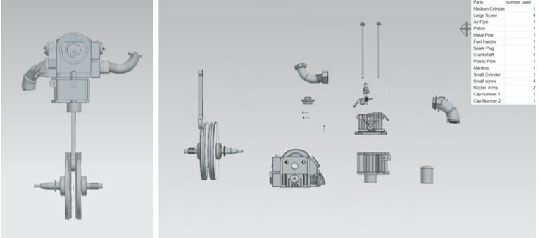
Exploded View:
Our object contains 28 unique parts and 41 parts in total. We have assembled 20 parts in our assembly file. We have assembled our parts mostly by concentric part constraints as in an engine most parts unite through pipes and holes. Another constraint we used was a slider constraint that was used to make our piston move inside the cylinder and finally we used the fix command to make sure nothing moved in a way we didn’t intend it to move. In total we have used 28 constraints in our assembly.
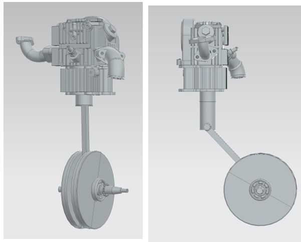
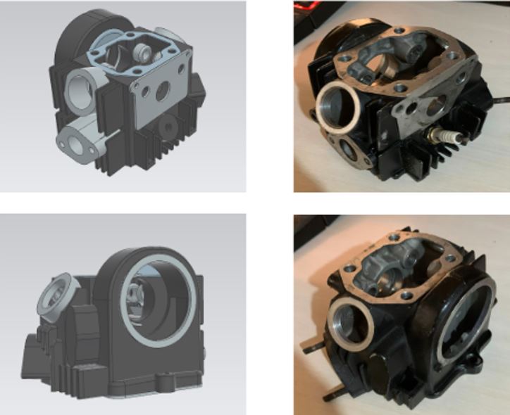
Part Comparisons and NX Commands:
Apart from the frequently used NX commands such as “extrude”, “hole”, “revolve”, “edge blend”, “pattern” etc. “sweep along guide” and “helix” commands were used for the spirals. The sweep-along guide took some time getting used to as it was earlier in the semester and it was yet to be covered in the class and PS sessions. The drafts of the spirals are not included in the report as they were much simpler compared to the ones here.
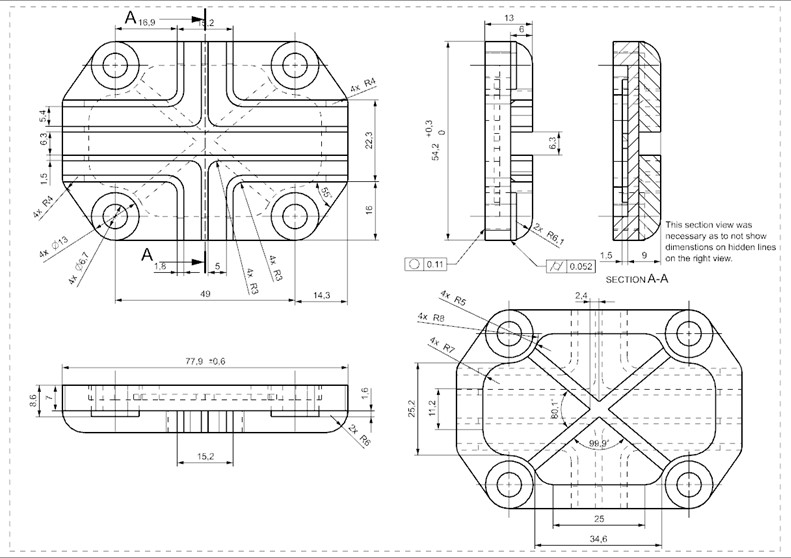
Drafting and Tolerances:
This part is one of the two caps (cap no. 1) that closes openings in the cylinder. The drafting for this part is important because it was one of the parts that we could use multiple surface tolerances on.
To give accurate circularity and cylindricity surface tolerances on this draft Deniz used drafts of similar-sized clearance holes she found on the internet as reference. She then used direct proportion to approximate the (mm) values displayed here. The dimensional tolerances were also not given at random. Since this is a cap and not a tightly bound piece, some dimensions were allowed to be larger and/ or smaller within a limit. However, certain lengths could not be shorter as this cap’s purpose was to close an opening in the cylinder assembly.