H. Noyan Nebil
M. Enes Topçu
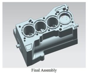
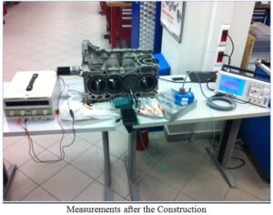
Our project is slider-crank mechanism based driven table, which is simply known as automobile engine. The materials of the project consists of are an engine block put vertically, which has pistons in it as segments, connecting rod, crankshaft and a DC motor, which has enough Torque to give motion to system.
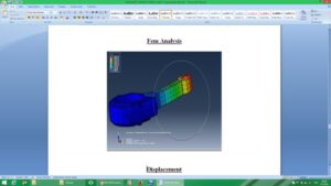
Our aim in the project is determining the acceleration, velocity and angle values and compare gamma contrast them with the theoretical calculations that we did. We have chosen a DC motor which is capable of changing the velocity by changing the voltage we feed to it.
In the mechanism the block is always stationary while the DC motor only has rotational velocity, in same time pistons having only horizontal velocity. Crankshaft also has only rotational velocity while rod having both rotational and horizontal velocities.
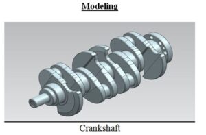
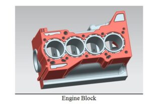
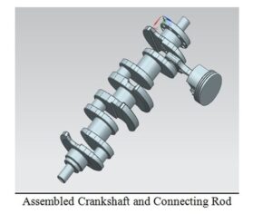
The engine that we used in the experiment is a Honda K-Series Engine Bottom-End. The block is a K20A2 european Honda Civic Type-r engine block which is 86×86 mm (bore x stroke) with an automatic transmissioned Clt accord crankshaft (K20A6) with accord piston connected with a Honda CR-V connecting rod. We made our decision through cut the lightest options when we choosing parts as well as cost and availability at the market. As Honda is known as ALL-MOTOR policy we decided going for it. We have chosen a crankshaft based on automatic vehicles than manuals because of the oil turbine at the transmission connected to the Flywheel also connected to the crank is to heavy and so we must decrease the weight of the total rotating parts in order not be overload our 24V electrical DC motor. We connected the electirical motor to the crankshaft after collecting all the parts using a part that we produced at lathe shop down at Baskinci Oto Sanayi. This was the hardest part for us because a tiny mistake in blance of the transfer material again may have caused on overload and ruin our project materials. After the assembly we moved to the calculations Unigraphics drawings and Lab analysis that is to be compared with theoretical part of the process.
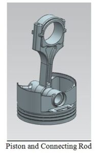
The base of dynamic mechanism operation of engine is slider-crank mechanism, which consist of crankshaft, connecting rod and piston. Combustion pressure transferred from piston (the part merely has reciprocating motion) to the connecting rod (the part has both linear and rotation motion) and finally to the crankshaft (the part has merely rotation motion).
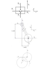
Kinematics analysis of slider-crank mechanism The engine slider-crank mechanism has been shown in Figure 2. The piston has linear motion in x direction in this figure:
x = rcos (θ) +lcos(β)
Where, r is the crank radius, L is the connecting rod length, θ is the crank rotation angle and β is the connecting rod angle with x axis.