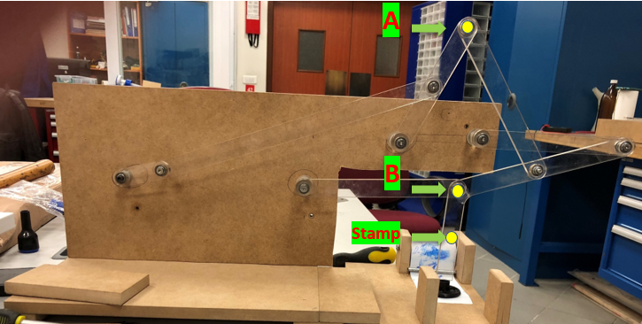
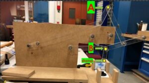
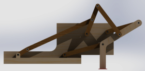
The project we were given is eight-bar stamping mechanism. Due its purpose the mechanism is a bit different than standard four-bar and five-bar mechanisms. There are six smooth bars and one curvy big bar (which we called bar 6), and the stamp is attached under the curvy bar. When the curvy bar is perpendicular to the floor, the stamp is in contact with the paper initiating the stamp where the paper is moving along a path with a conveyer under the mechanism. When the curvy bar is parallel to the ground, its pressing the inking pad to get ink from it for the next stamp. There is a simple working principle in this mechanism. We start moving the first bar (Bar number 1) which is constrained to rotate by the rod that is attached to the base. We decided to give the angular speed required to provide for movement with a stepper motor to be precise on positioning (see stepper motor section for further details). We are using the correlation of the angular rotations of the links connected to the first link. Also, there are 10 joints in this mechanism normally, but we changed joints with bearings. We thought using ball bearings will decrease the effect of friction so that the torque required would be less which is cost effective and loss of energy due heat dissipation is lower.
Meet Our Team

OZAN DIKEN
BURAK CAKAL
BERKE KURTCEBE
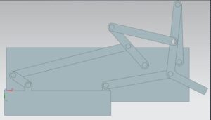
We started cad design with the smooth bars which are easy to design. The first thing we needed to find were the dimensions of each part. The stamping mechanism consists of 8 bars, the main body that is in contact with floor and the back side which is perpendicular to the main body. We captured a screenshot from an animation of the 8-bar stamping mechanism that we were provided with the project document. The capture was on YZ plane so that any measurements we make would be on 2D plane that makes the dimensional ratios amongst each other constant. Then we implemented a MatLab code to process the image that we upload to provide the ratios of links in terms of pixels where the parallax error due pixels nature of square is avoided. Later on, we imported the aforementioned screenshot into the MATLAB code we implemented, and we calculated distance with pixels.
All in all, we decided from the sake of manufacturing point of view of the whole bars to have 5mm thickness. Although bars have different length, every hole has almost the same diameter which is 12.8.mm which is the standard for the ball bearings that we decided to use. The clearance between ball bearings and laser cut diameter is negative meaning that there is a tight fit interference between them. There is 20.5mm distance between the parallel edges of the bars. The template of the smooth bars is same. We just changed the length of the bars to make another smooth bar. The distance between the two holes in bars are 46.7mm, 308.8mm, 131.5mm, 166.5mm, 349.7mm and 170.7mm in smooth bars respectively. There is only one difference in the template of the curvy bar (bar number 6). The curvy bar looks like the combination of two smooth bar with the intersection angle of 120 degrees. The angle is critical to have the stamping with right angle. It has also three holes which are same as others but there is an extra square plate at the end of it for stamping. The distance between holes is 181.7mm and the distance between hole and the stamping part is 104mm.
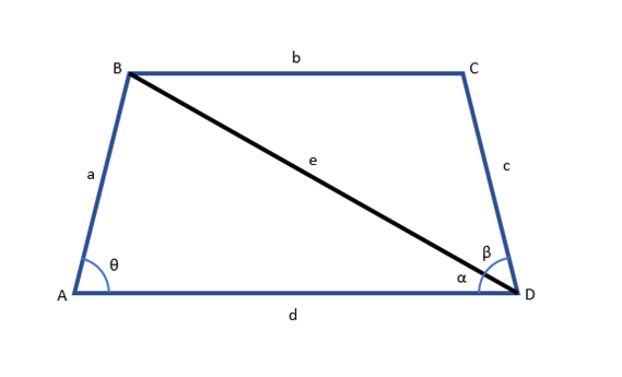
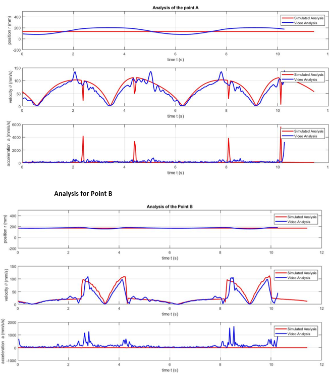
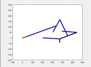
After we have calculated the angular positions for the given time with geometric interpretation, now we can use the dynamic equations to calculate the velocity and the acceleration of the specific points. For this, we need to know the angular velocity and angular acceleration for that rod. These values are calculated via numerical differentiation. In the MATLAB code, the built-in function “cross” is used to take the cross product. Since this function is only valid for 3-dimensional vectors, then we converted our arrays to the 3-dimensions via completing the empty elements by 0.So, we find all the angles to analyze the position of the all four points. At the and we can find the (x, y) coordinates of each point via projection on each axis. Now all needed to be done is produce a time domain and find all corresponding θ s. Then we can find all points for each second in a single Loop in the MATLAB. But in our project, there are two dependent four-bar mechanisms. To argue with more complex bar mechanism such as this, we divide the mechanism into two parts. Then we compute the second mechanism independently and store the data. Then we calculate the first four-bar mechanism in the loop and make the optimal decision for the rest of the mechanism from stored data, via comparison.
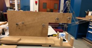
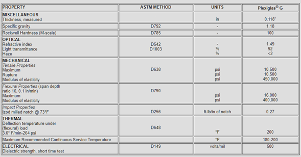
For material selection, we firstly selected plexiglass as bar material. The reason for the selection of the plexiglass is being not expensive and easy to shape by the laser cutter.
There are several reasons behind the choice of stepper motor over DC motor in our project: they deliver more torque which ensures the smooth rotational motion with constant angular speed and no angular acceleration which would be aligned with our analytical solutions hopefully. The stepper provides the control over the position of the shaft which was very helpful calculating the rpm values as a function of potentiometer adjustments and controlling our whole system at certain angles for some force measurements and adjustments accordingly. Another reason of a stepper motor would be it being more complicated to control than an ordinary servo motor. DC motors are controlled by varying voltage (switching arrangement known as H bridge for controlling via microcontroller)
whereas stepper motor needs a stepper motor driver card and microcontroller board to deliver [1, 0] signals also known as pulses.
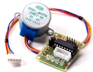
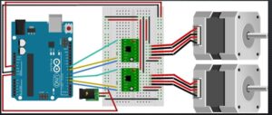
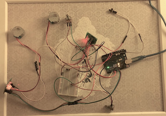
Arduino Uno is a microcontroller board based on ATmega328P with 14 digital output pins and 6 analog inputs. Arduino IDE has its own language that is very similar to JAVA which is then compiled into C/C++ when uploaded to the microcontroller for the setup. In bipolar stepper motors there are 4 driving pulses as demonstrated. A1&A2 and B1&B2 are groups of signals which are inversions of each other and the phase angle between two groups is 90 degrees in standard. Additionally, the frequency of the signals can easily be implemented within the Arduino code however then changing the value would require compiling the whole code once more into the Arduino and start all over again which was not desired. We rather used potentiometers for real-time variable control over the analog input of the Arduino to have the full control over the angular speed of both steppers separately. We were then able to display the potentiometer readings onto the Serial port monitor in real-time (with 5 ms signal response delay). With few mathematical implementations in the Arduino code we were able to convert the voltage values to the RPM readings which we had the full control over that eased our comparison with the analytical solutions. At the end we added a two-way switch to control the whole system for both emergency situations and turning the power on and off. All in all, whole electronics are ended up as indicated below:
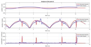
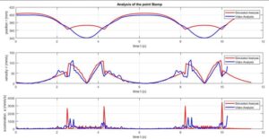
Video cameras work with the principle of capturing constant number of frames per each second and combine all to create the video shoot. With the information of fps (frame per second) value and change in time of the captured video, one can track a desired point within the frame and validate the position, velocity and acceleration of the point for 2D motion.