The project consists of design, assembly and manufacturing processes of a dynamic system and analysis of the motion in Matlab computing environment. This report provides information about technical background of the Spherical Watt-Six Bar Linkages system, mechanism design, CAD model creation, derivation of related dynamics equations, Matlab simulations and related codes, manufacturing processes and finally the discussion of theoretical and experimental results of the system dynamics analysis.
Meet Our Team

BEHCET BERK OZDEMIR
MERK AZAK
BUSE CAL
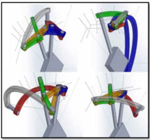
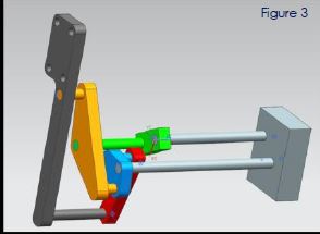
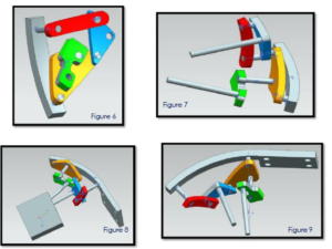
The mechanism is a six bar linkage mechanism that the bars are generated in spherical coordinates in SolidWorks. In our project after many trials and errors, lack of precision in the tolerances and dimensions of the bars, prevented mechanism motion to fully happen.
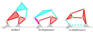
After moving on with a half motion assembly in NX 11, we tried to move forward to the manufacturing process. However, laser cutting machine in the manufacturing laboratory worked only on 2D designs. Therefore, we had to return back to the design and converted the project into 2D format. This retained the car door motion from a spherical curved motion of lifting. The revised CAD design motion only lift the car door in a vertical direction. A six-bar linkage is a one degree-of-freedom mechanism that is constructed from six links and seven joints. In general, each joint of a linkage connects two links, and a binary link supports two joints. There are two topologies defined on this topic: Watt and Stephenson six-bar linkages. In Sonawale’s design that we are inspired by, Watt six-bar linkage is applied. Watt’s parallel motion generator consists of the four-bar linkage that has a coupler curve that traces an approximately straight line trajectory, combined with a parallelogram linkage that copies this straight line movement to a desired location. This configuration of a six bars and seven joints has two four-bar loops.

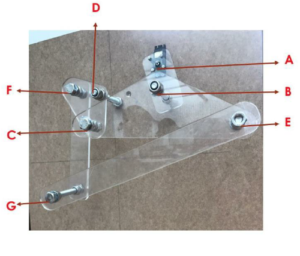
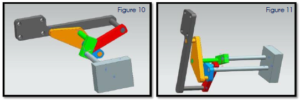
After making the final revisions, assembly is created in NX 11. Since six-bar linkage mechanism has only one degree of motion, we decided our motion point to be point A (where motor is mounted). In CAD design we used
pins to conjunct bars to each other while in manufacturing part bolts and nuts are used. When we create at point A, relative velocities and accelerations occur in other points of the system. We adjusted the motion to give 902D trajectory to point E (where car door is mounted).
In 2D format, we started designing the system part by part. We determine fixed two points. We did assembly with part by part. After completing one part, we added in assembly.
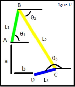
At the beginning, velocities of point A and D are known. We can calculate the velocity of point B directly because we know w1 which is created directly by servo motor.When, we calculate velocity of point C. We have two unknowns and two equations.
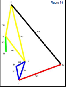
We started MATLAB programing with defining point’s coordinates. We have two fixed point and these points are A and D. They are our beginning point to defining. We are using analytic method to create other points with respect to fixed point.
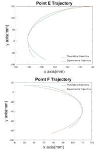
In MATLAB analysis, when we are using dynamic equation we can only get instantaneous velocity and accelerations from MATLAB code. For creating graph of velocities and accelerations we are using numeric methods. The experimental and theoretical positions and trajectories of points that we defined in our mechanism are shown in graphs for each points.