Ali Han Kılınç
Efe Tuntaş
İpek Sayıner
Mert Meral
Nida Sarıalioğlu
Introduction
-What is your project?
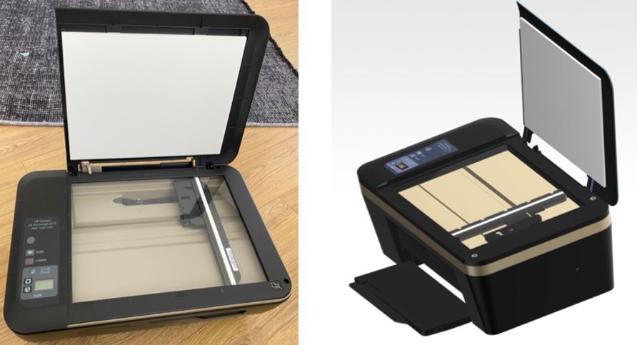
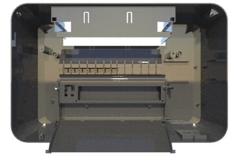
HP Printer Ink Advantage 2515
-What is it used for?
It is used for printing/ scanning documents
-How does it operate?
The Hp printer that we modeled is an InkJet printer which indicates that it functions by spraying in onto paper. The horizontal rod has a moveable arm attached to it which slides on the rod. The ink comes as droplets onto the papers through the nozzles. By the negative pressure inside the tip of the nozzles, it doesn’t allow the ink to leak. The print head and paper are able to follow such a precise path since they are controlled by a stepper motor and feedback circuit.
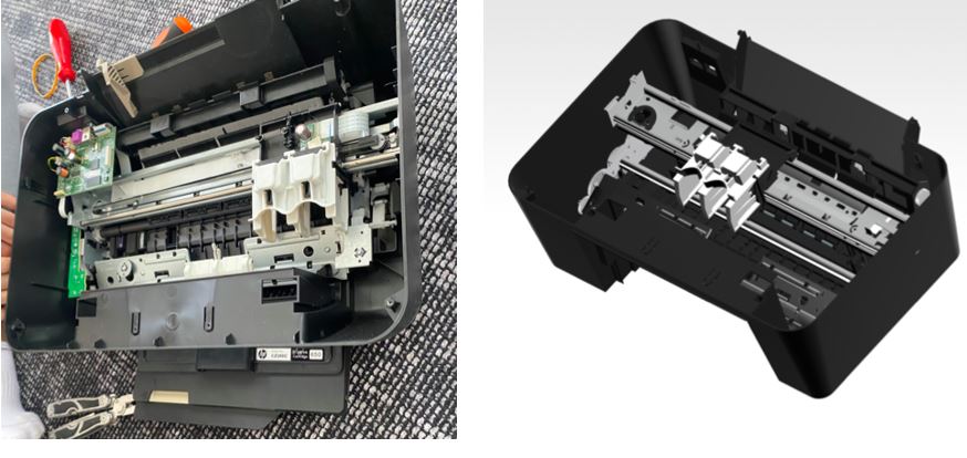
Disassembly
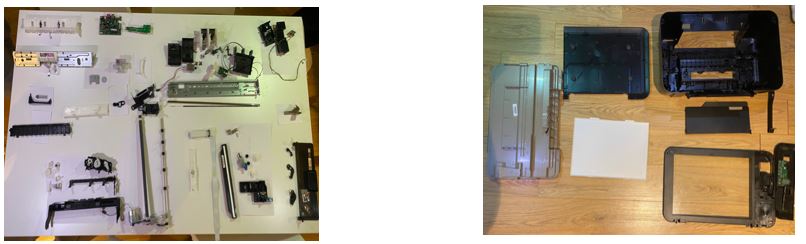
How did you measure the dimensions of your part? Did you face any challenges during the disassembly or measuring the dimensions? How did you solve those problems?
Printer parts were assembled in the beginning. As a group we started by disassembling the screws. The screws had narrow opening therefore a regular screwdriver was inefficient in the first place. We tried placing a cloth on the screw openings and twisting the scrwedriver on top. This method worked but then from the technical service we managed to find a suitable screwdriver with adjustable headings. All parts were connected to eachother with screws and placed inside of the main case. We grouped parts assembled together with the same index so that during reassembly, the final product would be accurate. Our device not only consisted of a high number of parts but they were all difficult to sketch on Siemens NX.
Exploded View
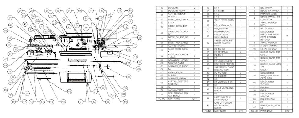
How many separate parts does your object contain? How many parts did you assemble in the assembly file?
Our object had 80 Unique parts and we modeled every single one. However during assembly we assembled 71 of the unique parts because of the fact that not every modeled part had a function. Team members approximately modeled the same number of parts depending on the complexity of the associated parts. We had 98 parts in total.
Part Comparisons and NX Commands
Show only a couple of your important parts or sub-assemblies. Talk about some of the different commands you have used while creating the part or constraints in your sub-assemblies. You can talk about extra features you have used here.
Part #1:
Sheet Metal Function was used to model the part. The difference of modeling using the sheet metal functions outstands at the point where “bending” is applied to the sides. Instead of a simple extrusion, we used “flange”, “bend”
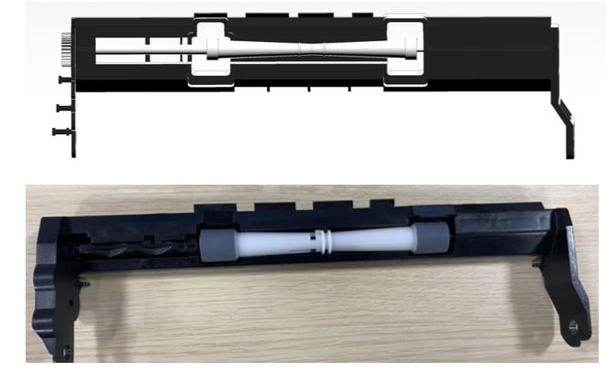
Part #2:
This is an assembled part consisting of a roller inside and the outer shell connecting to the main case. Revolve command was used in this part.
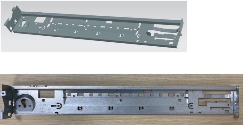
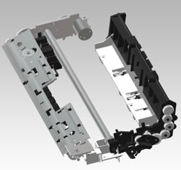
Part #3:
The main case of the printer where all the parts are going to be assembled on.
Part 4:
Assembled part of the paper intake body
Drafting and Tolerances
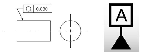
Talk about why the drafting for your chosen part is important. What surface and dimensional tolerances have you assigned and why?
Disclamer: We drafted all of our parts. Most of the drafts are present in the part files, however parts modeled and assembled on the student version were not saved in the original files. Therefore we added all the draft images to the “Draft Images” file.
The printer we modeled contains up to 80 unique parts and most of these parts are functional as a whole. For instance the motion of the gears turns the paper intake roller and then the paper slides. In a system which is correlated to tone another, accurate drawings are significant as well as adding dimensional, bilateral and surface tolerances.
We added tolerances to the gears, sheet metal surfaces, and covers.
Finite Element Analysis
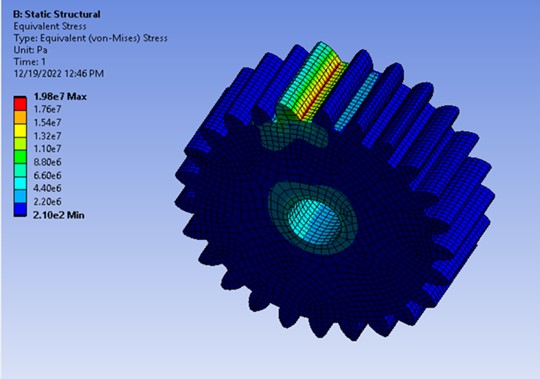
Talk about one finite element analysis you have conducted. What did you simulate? Why is this simulation important? Which type of simulation have you conducted? (structural, fluid, heat…) What materials did you assign? What are the initial conditions? (How did you fix it? How much loading on where?) What does that result tell you? (Where do the stresses accumulate? Where can it break?)
For the Finite Element Analysis, we chose to do a stress analysis for the worse case scenario for a printer: gears being stuck while the electric motor was still working. Depending on the yield stress of the material we chose (ABS plastic) and the power of the motor, we conducted a static structural analysis. After the analysis, we found out that even in this situation there was no plastic deformation in the gears.
Yield Stress ABS: 29.8-43 Mpa
102150 Nodes
Elements: 22496
Mesh Size: 2.06 xm