
Mustafa Doğan
Eren Ertem
Jamshid Jalilov
Baran Akgül
Pouya Moharramzadeh
Introduction
– What is your project?
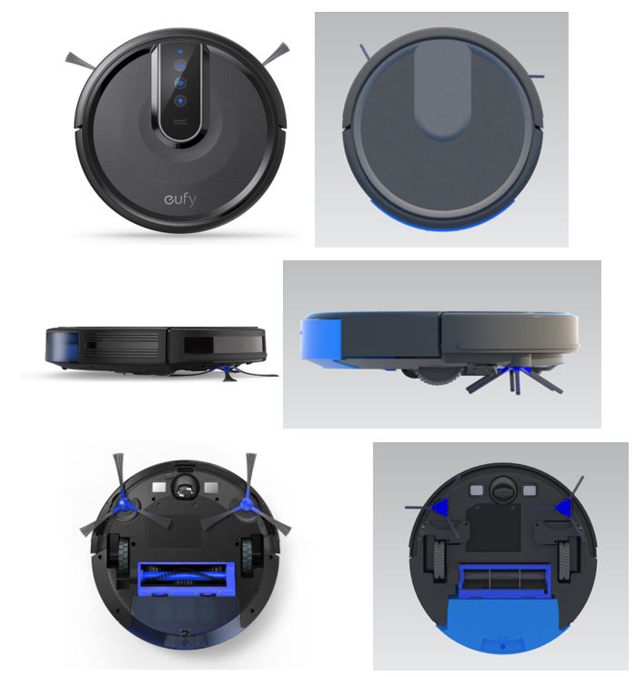
Our project is a robot vacuum cleaner
We disassembled the robot into small parts by hand at first. After disassembling, we took measurements and made solid models with technical drawings and sketches one by one. We learned during the project that creating a simple vacuum requires a great deal of processing, highly precise assembly of parts, and a foundation in the theoretical physics and engineering design we covered this semester.
-What is it used for?
Robot vacuum cleaner is the perfect solution when office hours are more numerous than those spent in your own home. They make our life easier, helping us keep home, workspace, etc. clean. It is used by most of us, mostly the ones who like comfort and don’t have too much time for cleaning.
-How does it operate?
Robotic vacuum cleaners use one or two spinning brushes along with a rolling brush. These brushes collect dirt towards the center of the room, where the electric motor creates suction. They use various types of sensors to detect and measure the worlds around them and their own progress through it, including cliff sensors, bump sensors, wall sensors, and optical encoders.
Real Image vs. Rendered Image
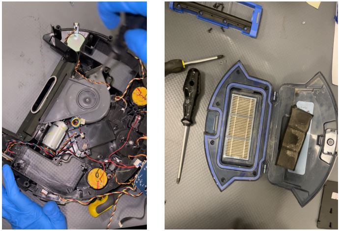
Disassembly
How did you measure the dimensions of your part? Did you face any challenges during the disassembly or measuring of the dimensions? How did you solve those problems?
Because some machine parts were so small, measuring the dimensions occasionally proved difficult. As a result, we took repeated measurements and updated them once more during assembly. Additionally, we used a new measurement technique that we independently discovered. Drawing the piece by hand on paper and taking measurements with different measurement instruments allowed us to determine the dimensions much more easily when we couldn’t use the caliper because the objects had curves that made the measurement difficult.
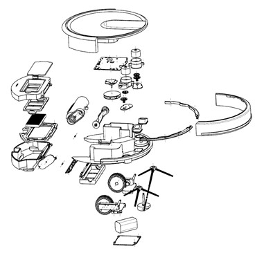
Exploded View
Part Comparisons and NX Commands
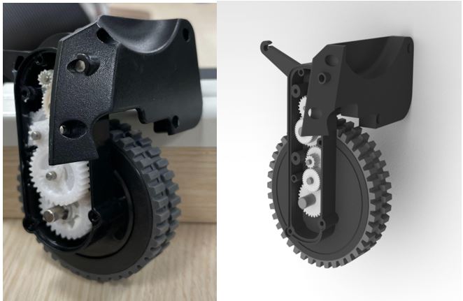
Main Wheel System:
This is one of the two main wheels which help robot vacuum to create motion. We mainly used circular patterns for both the teeth of the wheel and the gears. It helped a lot because the gear command kept crushing the NX and it could freely generate wheels with the desired dimensions and positions with the circular pattern feature.
Drafting and Tolerances
Main Wheel System Draft:
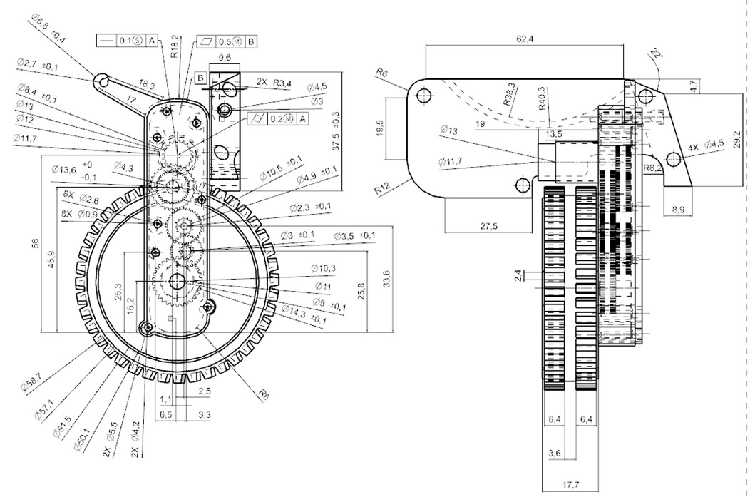
Cylindricity and straightness tolerances of the shaft are important because this shaft coming straight out from the dc electric motor and connected to the uppermost gear of our gear system. When we have a shaft which is not pretty much straight and cylindrical then, this shaft will cause serious deflection during its rotation. The gear connected to its end will move up-down or left-right so that the connection between the gears will be lost time to time and eventually the whole movement of the wheel will be interrupted periodically by this error and our vacuum cleaner won’t move fluently. Flatness tolerance of the axel surface is also very important because the axel cap needs to fit in the holes perfectly in order to be entirely closed. When we have a surface with a high tolerance of flatness, the holes on that surface will not match the pins and screws in the cap which will result a space between them.