
-İsmail Bora Üsküp
-Emre Ceylan
-Muhammad Saad
-Serkan Oğuz Çakar
-Taha Ağaçlı
Project Overview
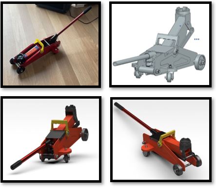
-Hydraulic jacks are generally made use of for automotive or general industrial purposes that require lifting, stabilizing or shoring.
-The hydraulic jack capitalizes on fluid pressure to create a dichotomy between input and output forces on differing surface areas of contact. This allows for lifting of heavy weights with relatively smaller input forces.
-For our project we chose a hydraulic car trolley jack. The jack has a lifting power of 2 tons and a lifting range of 130 mm to 375 mm.
Disassembly Process
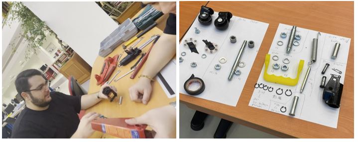
We dismantled the device using one of the workshops located in the Engineering building complex -2. We made frequent use of varying sizes of wrenches and pliers to pry the device open. Since the device components are very rough, it was hard to get an accurate reading on the components’ parameters. We bought vernier calipers for measuring small blends and engravings in the part including the various small holes that house the screws, and for the most part, we made sure to measure as accurately as possible considering the disproportional outlook of each part. We decided not to fully dismantle the piston cylinder as its inner structure uses drive fit to ensure little clearance and a tight structural fit. Due to this, the part was prone to deforming when dismantled, and it would be difficult to measure and model the part in such a state. The snap rings at the ends of the connecting rods were had to dismantle; this is partly due to their nature to clamp around the shaft. We lacked the special pliers commonly used to remove these, so we ended up using the thinnest pliers available at the workshop.
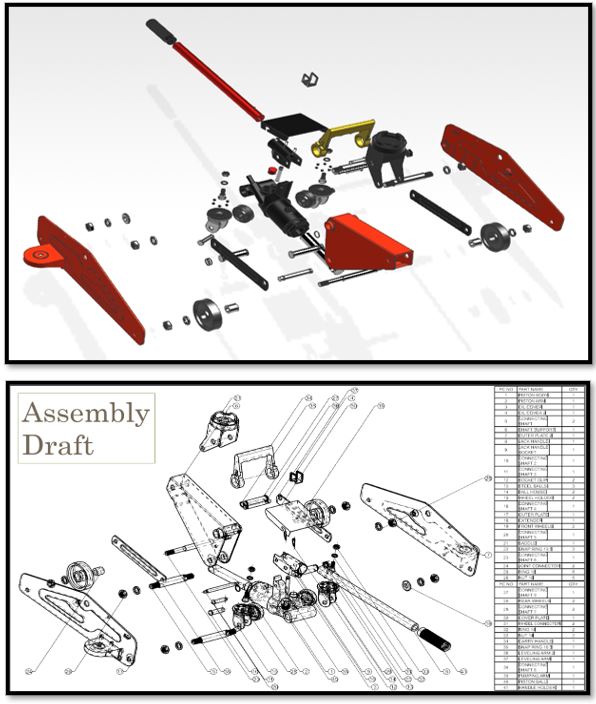
Exploded View of the Model
Our model has 41 unique parts (We considered the plates to be one unique part in our draft, however, there is a slight difference in the modeling of each plate including one feature unique to the left plate). In total there are 66 parts in our model. We assembled all of the modeled parts in the assembly file. We were unable to rename each part file due to issues with the final assembly.
Piston Assembly
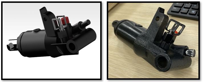
The Piston Assembly works at the core of the device to drive hydraulic fluid pressure and push the saddle up, hence creating the lifting motion we expect from the jack. The assembly consists of the cylinder component and the piston arm (plunger), with a reservoir for the hydraulic fluid at the back-end of the piston cylinder.
commands Used:
- Combine Curve Projection
- Sweep Along Guide
- Swept
- Hole (M16 Threaded)
Draft Sample (Piston Assembly)

For drafting the piston, we decided to use various form and dimensional tolerances. For instance, the piston arm needs to be smooth to successfully pass through the front cylinder opening. Hence, we set the cylindricity of the arm (plunger) to 0.05. This coincides with our tolerance for the front hole of the cylinder (H7). The shaft tolerance for the arm is g6. This way, we use a sliding transition fit (H7/g6) to allow for enough clearance for the arm to move back and forth through the cylinder’s hole.
Finite Element Analysis
For the analysis part of our project, we chose to conduct static structural analysis on the saddle of the trolley jack that comes in direct contact with the weight being lifted. The goal of this analysis was to gauge the amount of stress, elastic strain, and deformation experienced by the saddle and to find a possible solution for strengthening the saddle in hopes of reducing structural deformation.
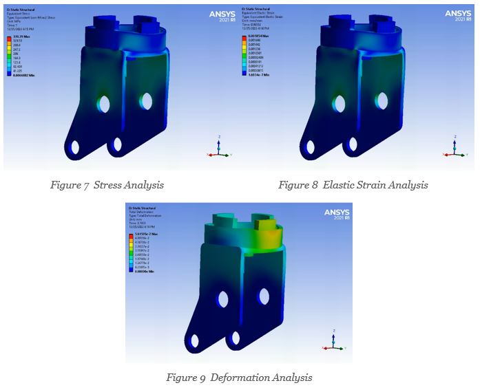
We didn’t use true-to-scale results, and the pictures above show exaggerated structural deformation of the saddle. This was done to show how multiples of the force we used could affect the saddle. The analyses show there is stress and elastic strain, particularly around the holes where the saddle is fixed. We extended the model of the saddle at the base by 20 mm to see if this would reduce the stress and elastic strain.