Ceren Ulusoy
Cemal Gayir
Selin Dinç
Tunç Yılmazer
Zeynep Güvenç
Introduction
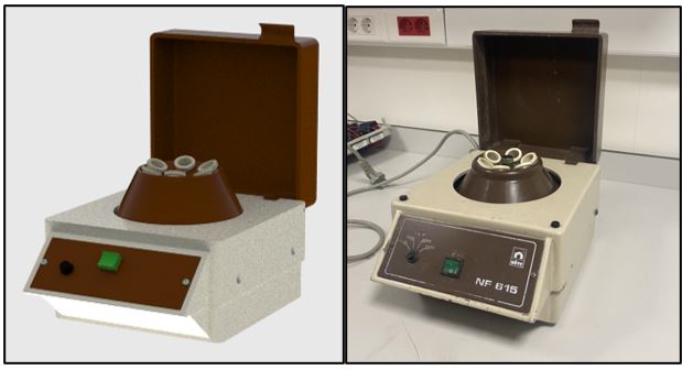
Disassembling, modeling and drafting of a centrifuge. Additionally, we have done an analysis for the rotary motion of the centerpiece and made some preliminary designs for the injection molding process.
Centrifuge is used for separating liquids with different densities in laboratories, generally in medical and chemical applications. Denser liquids accumulate on the bottom of the tubes because of centrifugal force.
It is operated by pouring liquids to the tubes provided, placing the tubes onto the rotary piece and selecting the desired rotation speed using the dial. Depending on the properties of the liquid, after a certain time has passed separated liquids can be observed.
Disassembly
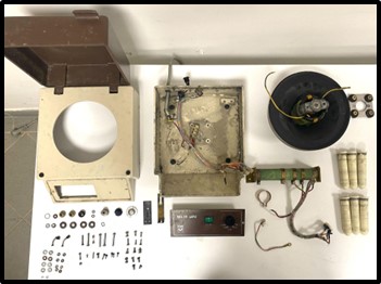
Exploded View
Our assembly consisted of 37 unique parts and a total of 106 parts. We also have 156 assembly constraints in total.
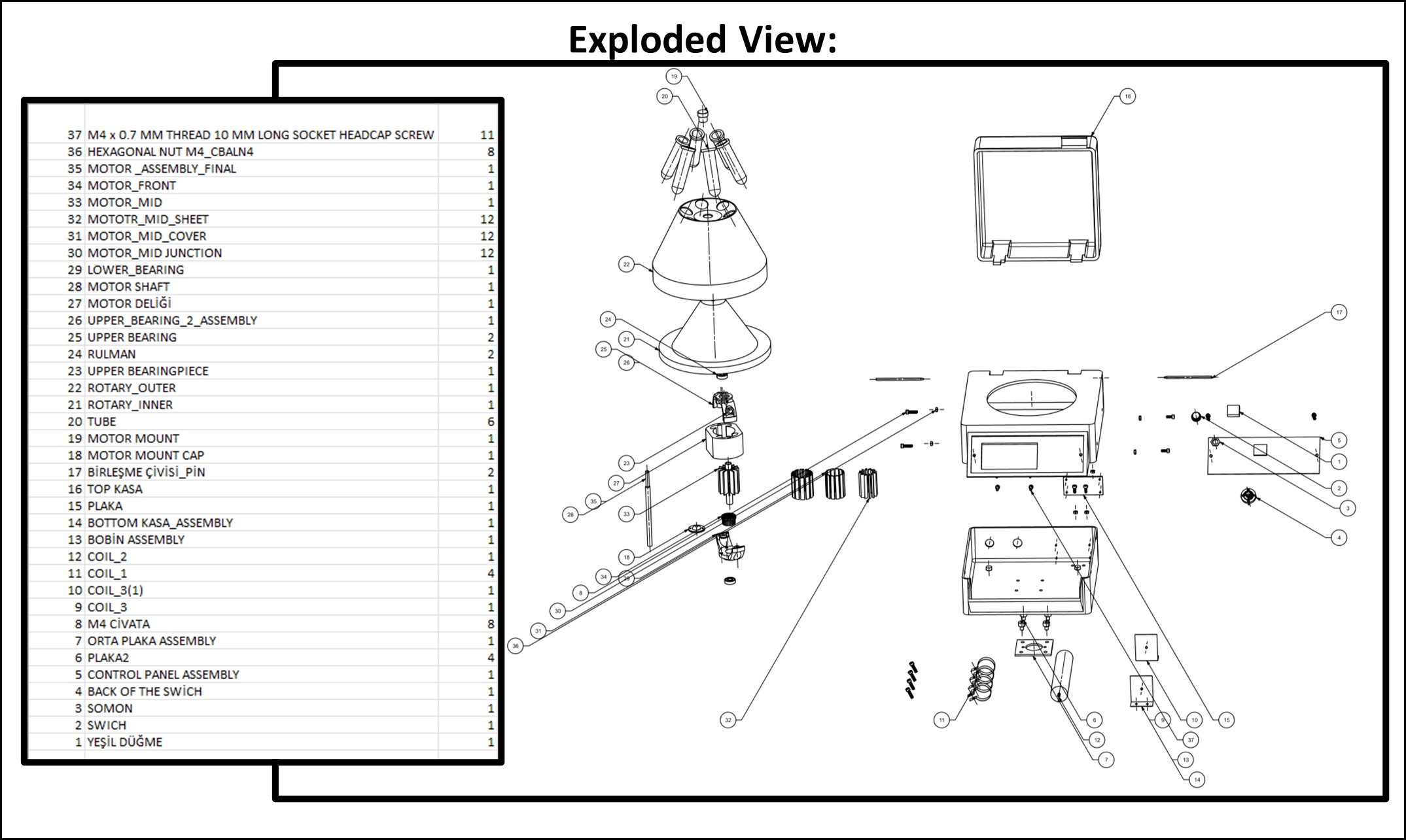
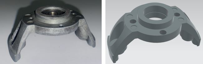
Part Comparisons and NX Commands
For this project we used multiple new commands, for example we used sweep along guide, tube and thread commands. Other than these we used the classic commands such as extrude, edge blend, mirror, etc. We re-modeled a few of our parts after learning about new commands to model the parts more realistic.
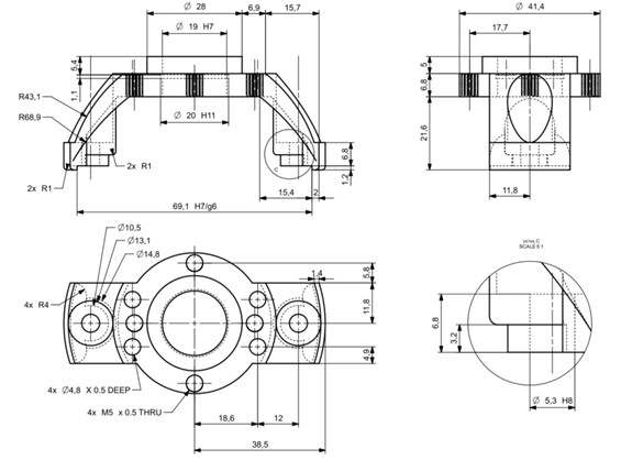
Drafting and Tolerances
The drafts on this report are highlighted because of the importance of tolerances designated on them for the application of our machine. We have tight dimensional and form tolerances specifically on parts that might introduce eccentricity to the rotary part and create critical stresses as we have shown in our FEM study.
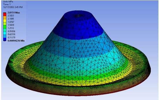
Finite Element Analysis
For the structural case we have compared two conditions: (i) no eccentricity (ii) eccentricity introduced through point mass of 1.5g (%1). Consequently, as stress results concentrated around the point mass region are critical for the plastic material, we have decided that tight tolerances are necessary in order to keep this from happening.