TEAM MEMBERS
DORUK KAVRAZ
BATUHAN CAN
WHAT IS A GENEVA MECHANISM?
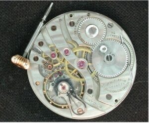
The Geneva drive or Maltese cross is a gear mechanism that translates a continuous rotation into an intermittent rotary motion. The rotating drive wheel has a pin that reaches into a slot of the driven wheel advancing it by one step. The drive wheel also has a raised circular blocking disc that locks the driven wheel in position between steps.
The name derives from the device’s earliest application in mechanical watches, Switzerland and Geneva being an important center of watchmaking. The Geneva drive is also commonly called a Maltese cross mechanism due to the visual resemblance.
WHERE IS IT USED?
Geneva wheels having the form of the driven wheel were also used in mechanical watches, but not in a drive, rather to limit the tension of the spring, such that it would operate only in the range where its elastic force is nearly linear. If one of the slots of the driven wheel is occluded, the number of rotations the drive wheel can make is limited. In watches, the “drive” wheel is the one that winds up the spring, and the Geneva wheel with four or five spokes and one closed slot prevents overwinding (and also complete unwinding) of the spring. This so-called Geneva stop or “Geneva stop work” was the invention of 17th or 18th century watchmakers.
One application of the Geneva drive is in movie projectors: the film does not run continuously through the projector. Instead, the film is advanced frame by frame, each frame standing still in front of the lens for 1/24 of a second. This intermittent motion is achieved using a Geneva drive.
Other applications of the Geneva drive include the pen change mechanism in plotters, automated sampling devices, indexing tables in assembly lines, tool changers for CNC machines, banknote counting and so on.
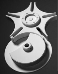
In the most common arrangement, the driven (Geneva) wheel has four slots and thus advances for each rotation of the drive wheel by one step of 90°. If the driven wheel has n slots, it advances by 360°/n per full rotation of the crank wheel. However, our project has five slots, so it advances by 360°/5 = 72° per full rotation of the crank wheel.
DISCUSSION
As on graphs, there are some differences between the theoretical and practical values. In this part of the report, we discuss the reasons of those differences. The first reason is that the crank wheel loses its speed when it touches the Geneva wheel. However, from the beginning we always assumed that crank wheel has a constant angular velocity, but in real, it does not. Sothis caused some error on our graphs.
Secondly, because there are only seven frames in between -54° and +54° of θ, we could take only seven data on that range. If we could have taken more than seven data, the results would have been closer to each other which would make the practical graph look smooth. However, we could take seven data. That is the reason why the practical graph looksuneven.
Last but not least, there could be some manufacturing errors such that there could be some parts that are not smooth or straight. Friction is readily neglected in our project, but those “not smooth” areas could cause extra friction which could lower the speed of our wheels in an unpredictable way.
CONCLUSION
As mentioned above we obtained accurate results by using simple techniques. We recorded the motion of the system with a camera, which is a basic technique, and using the Adobe Premier Pro program we could easily take the data that we needed. We also learned that the Geneva Mechanism is widely used in the industry. When we compare our practical graphs with the theoretical graphs we saw that even though the results are close, the practical yield is always smaller than the theoretical yield. As a conclusion, when building a system like Geneva Mechanism, there are always some errors but by using basic techniques those errors can be predicted and overcame.