TEAM MEMBERS
Ozan Ülker
Oğulcan Alcan
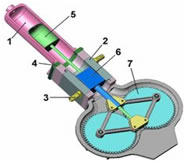
The rhombic drive is a specific method of transferring mechanical energy, or work, used when a single cylinder is used for two separately oscillating pistons.
In its simplest form, the drive utilizes a jointed rhomboid to convert linear work from a reciprocating piston to rotational work. The connecting rod of the piston is rigid as opposed to a common reciprocating engine which directly connects the piston to the crankshaft with a flexible joint in the piston. When force is applied to the piston, it pushes down; at the same time, the outer corners of the rhomboid push out. They push on two cranks/flywheels which cause them to rotate, each in opposite directions. As the wheels rotate the rhombus progresses its change of shape from being flattened in the direction of the piston axis at top dead center to being flattened in the perpendicular direction to the piston axis at bottom dead center.
First of all , we did the research about rhombic drive mechanism. We found couple of articles and we start our project based on these articles.
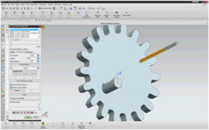
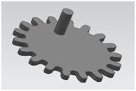
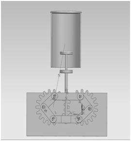
After that we wrote a Matlab code to obtain parameters that we are going to draw on Nx-Siemens because at the beginning we don’t have any sketch. After the Matlab code we obtain some measurements which is proper for our project and then we start to draw our components on Siemens Nx. The most hardest part is drawing the gear because there must be relation about the inner – outer diameter and the number of the teeth and also there is not a ready pattern for gears in Nx-Siemens so we did the calculations first and then start to draw it.
When we finished the drawings , we started to assembly our parts. We have some problems while assembling our parts that is why we couldn’t use Nx Motion Simulation property , however then we fixed it. Here is the our final assembly;
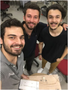
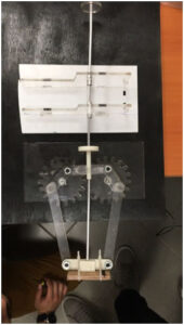
When we finished our drawings , we came to the our TA and we start to produce our parts in 3D-Printer. For some parts which is not possible to produce it with 3D-Printer , we used laser-cutting. When we finished our production part , we also used milling-drilling machines and also saw to give a certain shape to our materials. Moreover, in some parts, we use guide pin to produce a way to our screws. We used Plexiglas adhesive two times for fixing the Plexiglas on our gear. Most of our parts produced by Plexiglas because it is easier than any other material. Here is the our final project,
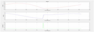
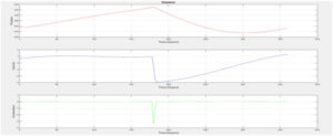
Meanwhile , we were also doing some simulations on matlab and we obtained position-velocity and acceleration profiles with respect to the time. These were the our theoretical results and when we completed our project we applied MaxTRAQ Analysis to compare our theoretical and experimental results. Here is the our theoretical results from Matlab;
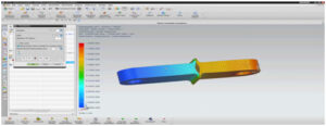
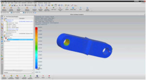
When we finished our theoretical and experimental graphs , we start to do some analysis. We did these analyses because we want to see how is going to change our material. So we chose one of our links and start to apply 5 Newton. From Nx Siemen’s properties we applied Displacement Analysis, Stress Analysis and also Reaction Force Analysis. We obtain reasonable results from these analysis and below the photos of these analyses,
Displacement Analysis;
Stress Analysis;
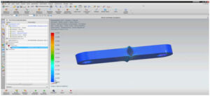
Reaction Force Analysis;
When we finished all of these steps , we want to make a short video about , process of producing gear and we use CAD from Nx-Siemens to see how it works. We followed Roughing –Semi finishing and Finishing steps and we used Cavity Mill for Roughing , Floor Wall for Semi finishing and Contour Area for Finishing. Lastly we use appropriate diameter mill instead of ball mill. Here is the our Manufacturing process of gear;