TEAM MEMBERS
Derin Bilen
Damla Yengül
What is transmission?
Transmission is the process of changing the speed ration between the engine and the wheels of a motor vehicle.
What is CVT?
CVT, standing for Continuously Variable Transmission, is a type of transmission designed to provide a continuous range of gear ratios. In a regular automatic transmission there are typically only 4 forward gears.
The Advantages
Because there is no shifting between discrete gears the ‘jerk’, or shift shock, is not felt in a CVT based vehicle. Also a continuous transmission allows the engine to work uninterruptedly as well making it more economical fuel-wise. It is also lighter and more compact than a regular transmission system.
How it Works
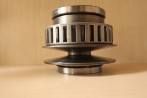
The most common type of CVT consists of two pulleys and a belt that rides between them; the primary pulley is attached to the motor and the secondary pulley is attached to the wheels.
The pulleys are made up of two conical pulleys facing each other and while both are able to rotate only one has axial motion. The system works in a way that as on of the sheaves of a pulley moves one way, the sheave of the other pulley simultaneously moves in the opposite direction. In a regular car this ‘back and forth’ motion is created with hydraulic pressure. Through this motion the belt either moves up or down on the pulley and as a result the rotational radius of the belt at each pulley changes as well. While the rotation on the primary pulley remains constant, the torque and angular velocity on the secondary pulley changes in relation to the radius thus allowing the wheel to receive a controlled rotation.
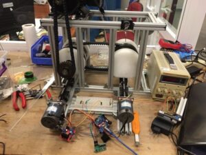
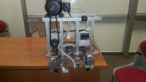
Our project consists of ;
❖ The two pulleys of a Nissan Juke
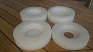
❖ Rubber belt
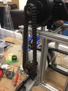
❖ Chain mechanism, used to deliver the power from the motor to the primary pulley while also decreasing its torque with a 1:2 gear ratio.
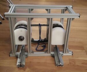
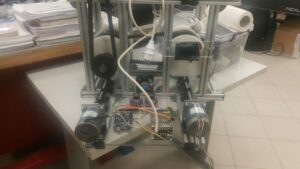
❖ Aluminium profiles, used to align the pulleys and keep them in a stationary position that allowed them to rotate.
❖ Mono-phase motor, the source of the power.
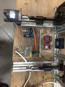
❖ The axial motion of the two pulleys where created by attaching a step motor to both and using Arduino codes to control them. A mechanism of linear bearing, infinite screw and flexible coupling was used to turn the rotational motion of the step motor to a linear one.
❖ The electrical circuit also included;
❖ An adaptor
❖ Heat Sink
❖ Fan
❖ L298N Motor Shields To collect experimental data a system that measured the angular velocity of the secondary pulley was built using;
❖ DF Robot LCD Shield
❖ Infrared counter
❖ Arduino Uno