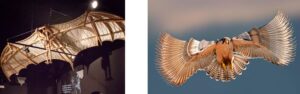
Our project was ‘the Flapping Wing Mechanism.’ We were expected to design a simple project that transfers circular motion into linear motion that would flip the wings. At first, our aim was to make a real flying mechanism, but after our researches and designs, we figured out that it was harder than we expected to overcome the weight of all parts and motor. So, we decided on doing a project of a bird standing still, where we transmit the circular motion of gears into linear motion as flapping wings of the mechanism.
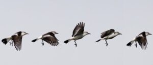
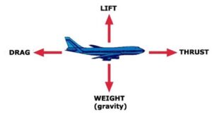
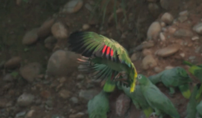
There are four fundamental forces in the world. In order to fly, the lift force has to overcome the total weight. As we have observed birds fly and watched many videos on flying animals, a typical flying behavior consists of flapping and pitching motion. Meaning that, a bird can lift itself up, by creating a levitation and move itself to right and left as it wanted, by controlling the motion to the sides. The flapping motion is not just the movement of the wings downwards and upwards. If it was like this, the bird would remain at its previous height, unsuccessful to take off and land back on the ground. That’s why a regular bird pushes the primary feathers downwards with a deviation, so that the final push of the wing creates a levitation that actually moves the body upwards. We could just merge two simple rods to each other and connect them to a gear to create a flapping motion, but as we wanted to biomimicry a pigeon, we wanted our project to look like as real as possible.
Meet Our Team

MUSTAFA ALPKAN INCEGON
SUKRAN IPEK KENAROGLU
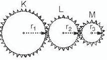
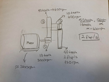
A pigeon, at an average flight, flaps its wings 1 flap per second. We needed a power supply, a motor in our case, but the rotation speed was too high in motors. So, we had to decrease the velocity to 1 flap per second. But how, was the question for our starting point. We checked the previous projects from last years and saw that gears were used. So, we decided to use gears with different diameters as well, in order to keep the linear velocity same but have different angular velocities. As seen on Fig. 2, the number of teeth increases as the radius increases. We took advantage of radius (r) dimension differences. ‘n’ representing the number of revolution, the product of ‘n’ and ‘r’ of each gear gives us the same number as seen in the equation below.
![]()
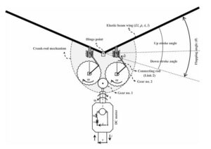
First, we chose our motor. We needed a DC Motor with a 3000 – 4000 rpm, and we bought one with 3000 rpm. But we needed a design to reduce the velocity up to 1 flap per second. So, we drew a primitive draft Fig. 3 as the beginning point. We had to connect the motor to a small gear and rotate a bigger gear, to reduce the revolution per minute, and needed a similar couple to reduce it by half again. As we started designing, we figured out that it would be easier for us to put only one small gear next to the motor and mesh its teeth with only one big gear. Because if we were to place the small gear to mesh with all big gears at the same time, we would have friction problems for sure and our mechanism would fail within seconds. Then, we put an identical gear to the other side to maintain a symmetrical and a synchronized motion.
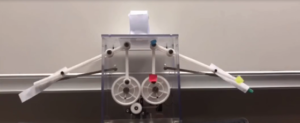
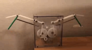
We needed an eccentric rod, that was connected directly to the gear and rotate with it. This rod would move up and down with a curvilinear path causing the following rod to move also up and down, linearly. But a primitive design was not enough for us, as we wanted to enhance our project and put on more effort to it. So, we designed a second wing and decided to manufacture and assembly them at the same time to give chance to the audience to compare them at the same time.
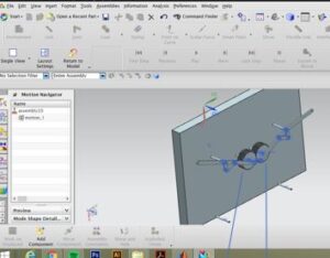
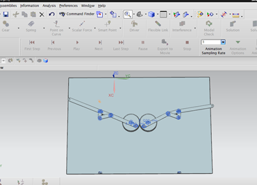
We used Siemens NX for designing part of the project. As we didn’t know the secret gear creator, we spent more than necessary time on creating our gears. First, we drew them manually after we did many researches on teeth ratio, dimensions of gears and relation between teeth dimensions and the center. But the gears didn’t mesh on NX, so we tried it for 3 more times. Then we figured out the gear creator and moved on to designing rods as in Fig. 4. As we did biomimicry a pigeon, we didn’t want our wingspan to exceed 500mm, so we decided on our dimensions of rods. We used basic commands, such as sketch, pattern, extrude, curve, and trim.
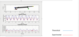
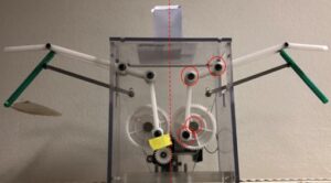
We used to calculations from Chapter 16. We specified 2 critical point for calculations and comparing.
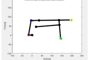
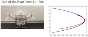
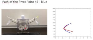
Red and yellow which are A2 and D points are our critical points because these points have trajectory motion. Their tends to environmental affects are more so comparing in analyzing process is more complicate. We wanted to clear these difference. By mading calculations, we used firstly formulas from class then position, velocity, accelaration. In this point, MatLab joined the project process.
In calculation process, we had to simulate the system in MatLab. We firstly specified constant points. The main problem was about trajectory movement points. Their positions change according to gears’ movement. So, we had to enhancement a relation between gears and rods. Our beginning point is gear’s angle. When it rotates, its angle changes between 0 and 2*pi. In all system, we have 4 unknown angles. a, b, m and s angles. We had to find relations between these angles and main angle q which is gear angle. We used Newtons Method twice to find these unknown angles. By these method, we can observe a, b, m, and s values according to q changes. By this, we can find rod’s position in motion. After that, we have to simulate these points. “plot” comment is need but it is not a stabile graphic. It must change according to angles. So, we used “for” loop. MatLab made draw and delete the rods by the time and simulation is observed.
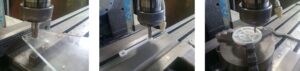
We were lucky to find our big gears dumped out of a copy center. They were identical and 65mm in diameter, just as we needed. They were out of polyamide, which we also used for other parts of the project because the material was light, cheap, and easy to manufacture. Then, compatible with the big gears, we manufactured the small gear by a turning machine with the same material and one third dimensions, in order to reduce the velocity from 180 rpm to 60 rpm.
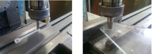
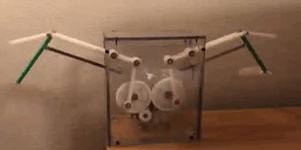
Again, out of polyamide, we manufactured all the rods starting from the eccentric rod in Fig. 5 and drilled holes in them later to put bearings. Our end rod at the second wing at the back is green on purpose, not because it is out of a different material, but to get the attention to its final push motion, which leads to levitation. We wanted to make it obvious to see the difference between the primitive and the enhanced wings by color variation. The second material we used is plexiglass because we needed a strong but transparent material to protect the mechanism and let us see through. On Fig. 6 you can see the holes drilled to immobilize the parts. We assembled the parts by bolts and nuts. We also used 12 bearings in total because we cut down the friction and supplied multi-dimensional motion in the system.
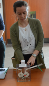
After that, we observed the manufactured prototyped. We named points same and record the motion of prototyped by camera. By doing these, we used colored stickers.