Feeding-cutting mechanisms are composed of two different parts, which are feeder and pointer. The feeder part is the crucial one since it maintains the continuous paper flow for the processing. Pointer part is also important since it makes the real part of process; however this part is optional which means that can be replaced easily with other parts such as stamp or cutter. Feeding mechanisms can be seen very frequently in many daily devices, such as ATMs, copiers, printers, and minting process.
In a detailed perspective, cutting-feeding mechanism consists of two different four-bars. In order to make dynamic analysis of the cutting-feeding mechanism it is very important to understand the four-bar mechanism. One of the most important points of the connection is their degrees of freedom between four-bars and the whole mechanism. The degree of freedom of four bar mechanism is only one, so it means there is only need for one information of one input, which will be, in this project, the angle between fixed frame and shaft. As a result, the cutting feeding mechanism has one degree of freedom. 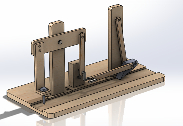
Meet Our Team

BERKAY TERZI
MERT TOPSOY
Four-bars are one of the most used mechanisms among most of the daily devices such as bicycles, door frames and so forth. This simple mechanisms, as their names implies, consists of 4 bars, which are named as frame, crank, coupler, and rocker. Crank is the bar that connected to the motor which is the movement source, and usually the operational part is the rocker bar. Depending on the lengths of each bar, it is possible to decide the movement of rocker.
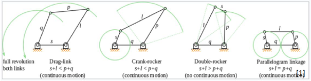
In terms of cutting-feeding mechanism the crank-rocker four-bar mechanism is used , whose crank makes continuous motion while its rocker cannot make full rotation. This crank-rocker four-bar mechanism is used for both pointer and feeder part for continuous motion of the full cutting-feeding mechanism.
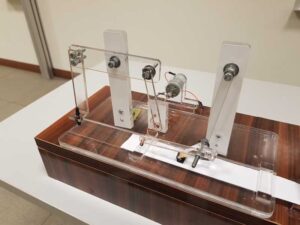
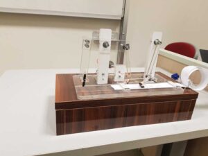
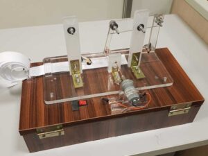
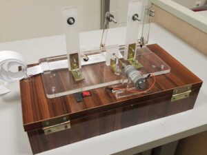
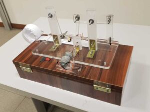
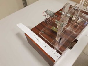
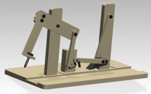
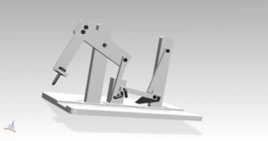
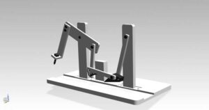
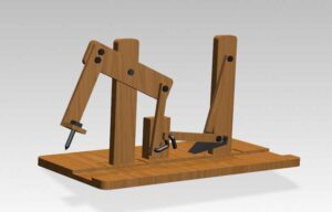
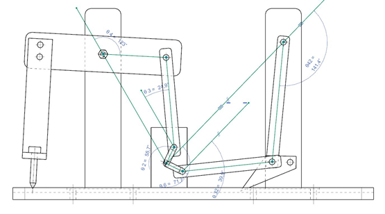
The design of the feeding-cutting mechanism was made in Siemens NX 11.0. The operational parts are; Pointer and Feeder, as can be seen from the figure. The feeder part continuously pushes the paper that was put on the path by the user, and maintains the flow of the paper towards pointer part. The pointer part is designed to leave a mark on the paper periodically.
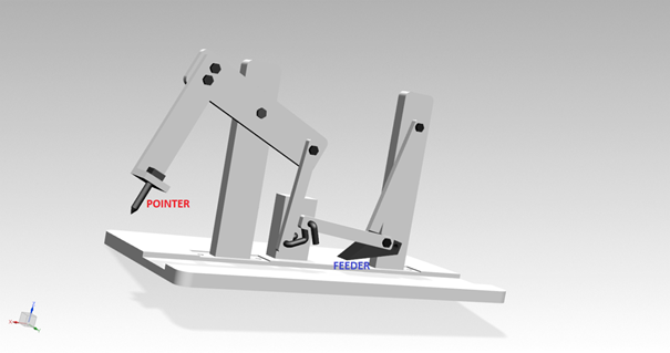
In this project, the continuous motion of the whole system is provided by two different crank-rocker four-bars.
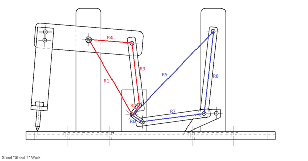
In the figure it can be seen that; while blue four-bar provides continuous motion for the feeder part, which is designed to push the paper towards the pointer part, the red four-bar provides continuous motion for the pointer part.
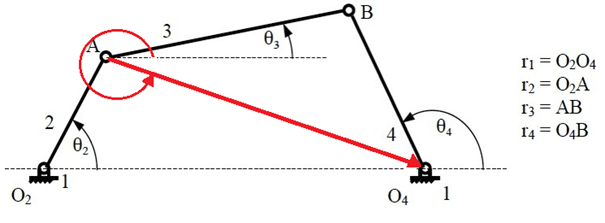
Here, two “θZ” values are obtained. However, “θZ” is always in the first and fourth quadrant. So, arcsine value of “θZ” was chosen. In the same way, two “θ4” values are obtained. However, “θ4” is always in the first and second quadrant. So, arccosine value of “θ4” was chosen.
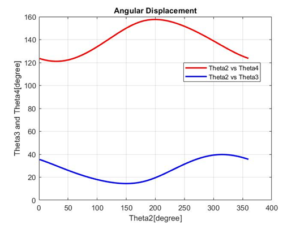
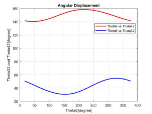
Before starting validation part, it is important to make sure that position analysis of mechanism should be meaningful. In order to prove that dynamics equations are valid and correct, there is a comparison between CAD Model angles and theoretical results.
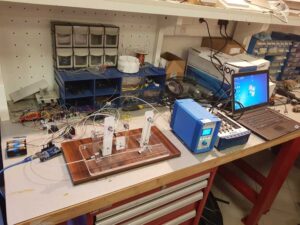
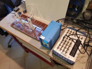
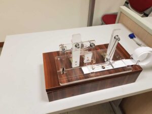
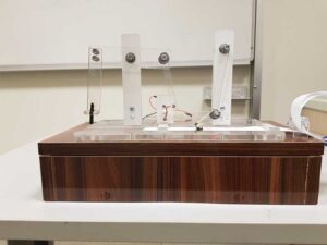
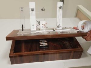
While manufacturing the mechanism, some parts are slightly changed in order to get better results. In CAD design it was thought that all plexiglasses are connected with screws, however it was possible to crack the plexiglass while screwing it into the main plexiglass part. So, it was better idea to use drilling machine while perforating in order not to crack plexiglass. After drilling all specified points, socket screws and lock nuts are used to connect all parts. Vertical plexiglass parts are connected to main parts with “90 Degree L Shape Metal Corner Bracket Brace Support Holder”.
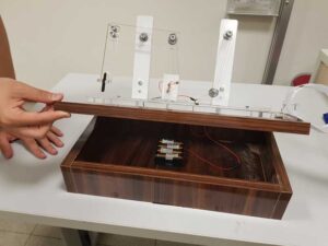
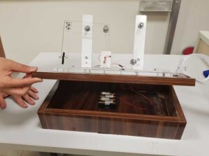
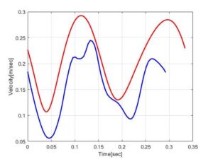
To be able to adjust the RPM of DC Motor, Arduino is used. For this project,1 DC Motor, 1 L298-N Motor Driver and 1 Arduino UNO are used. Thanks to changing the voltage, we can adjust our mechanism’s RPM. Without weight, DC Motor provides 200 RPM. However, after we setup whole mechanism, DC Motor’s RPM decreased to 180 RPM.
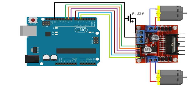
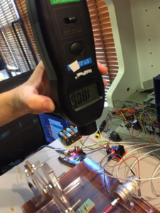
In this project, non – contact tachometer was used to determine angular velocity which is provided by DC Motor. Without any weight, DC Motor can provide up to 200 RPM. However, in experiment, tachometer showed that under weight of bars, screws and sockets, DC Motor could provide until 180 RPM. This data was used as input for angular velocity calculation.
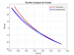
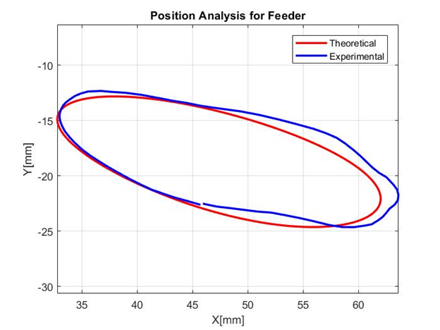
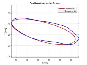
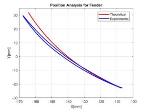
In project, MATLAB Path Tracer is used for determining the position of the tip of pointer. According to theoretical values, system should move 58 mm towards right and 50 mm towards up. These theoretical values are obtained by calculating θ4 and θ3 and bar’s length. Basically, colorful paper was put to place that will be calculated. After entering the color scale of paper, MATLAB automatically follows the path and creating a graph for positions. Comparison between theoretical values and experimental values is done by group members. According to graph, mechanism works well except 2 mm vertical difference. 2mm difference can be neglected since mechanism path should be around 50 mm. Also, error rate is %4 for vertical motion of pointer. For horizontal motion of pointer, experimental results are similar to the theoretical results. The difference is because of shaft’s horizontal dimension.