The piano action mechanism (also referred as the key action mechanism or simply the action) of a piano or different musical keyboard is the mechanical assembly which translates the depression of the keys into rapid motion of a hammer, which creates sound by striking the strings. An expert pianist is most likely to concern about the piano’s action, since that is the thing which controls its responsiveness and relative softness–or heaviness–of touch. A piano’s action is light when its keys fall effortlessly beneath the fingers, and heavy when an observable descending push is required. The action, to put it plainly, is what makes a piano playable or not to an individual musician. The piano action was the key new addition that Bartolomeo Cristofori created when he invented the piano in 1698. It utilized levers to amplify the little movement of the piano key into an extensive movement of the hammer.
Meet Our Team

CAN OZCAN
DORUK BILEKE
ONUR PIRLANTA
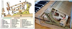
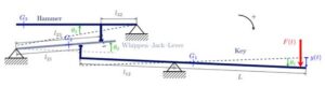
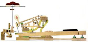
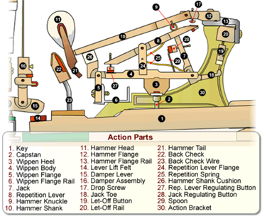
The Key (1) is pushed down by the pianist’s finger. The angular velocity varies but the angular displacement is constant. As the key is pushed down, the Capstan (2) pushes the Wippen Heel (3) up, which lifts the Wippen Body (4). While the wippen body rises, it lifts the Jack (7) and the Repetition Lever (8), which work together to push the hammer towards the string. The jack and repetition lever pushes the Hammer Knuckle (9) which rises the Hammer Shank (10) and Hammer Head (11). After the hammer shank and hammer head goes up, the Jack Toe (18) meets the Let-Off Button (19). The let-off button makes the jack to rotate about the hammer knuckle – at this point, the hammer continues to move upwards to the string- from now on the hammer doesn’t touch any part of the mechanism. This process is called single escapement and it allows the hammer to rebound immediately from the string while the key stays down. Without escapement, the hammer would stay with the string and prevents any vibration.
There is a special state called halfway release mechanism. Halfway release mechanism does not affect the working of the mechanism directly but adds an advantageous feature. Halfway release action happens so fast that it is hard to catch it with bare eye. The best way to observe is holding key down.
After we tap the key and hold our finger down, hammer first hits the piano wire. After that while it falls back it is held with the back of the key. This small maneuver is called halfway release action and it makes hammer’s fall smoother, prevents unwanted out coming sounds from a crash between hammer and wippen.
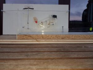
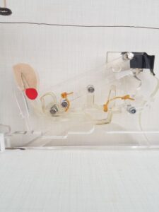
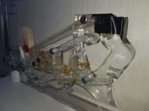
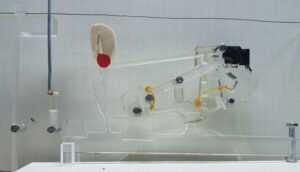
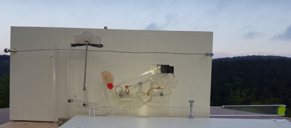
We took references from ‘‘The Piano Deconstructed’’ Master Degree in Music Technology of Christopher Smit for University of Indianapolis and then we adjusted the CAD design according to our manufacture process. The design was not suitable for the laser cutting process, we made adjustments on SIMENES NX according to make it suitable for laser cutting process to maintain a constant thickness since laser cutting machines works only two dimensional. We measured a real piano key’s dimensions and used Scale Body function according to that before manufacturing. Since we could not find or manufacture a repetition spring, we used elastic bands to make the repetition lever and the jack to come back to their initial positions. Because of the friction between two, we need to use elastic bands to ensure the mechanism functions. We used copper wire instead of a real piano string since it was too hard to stretch. Also, we decided to use wooden blocks as a base to have durability and vertical support to stretch the string in our mechanism.
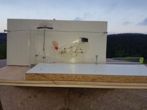
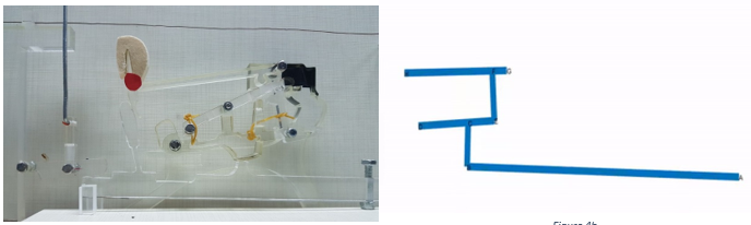
We start with producing our parts by using laser cutting machine. Since we have parts each get through by each other and since we need to produce them with constant thickness, we had to machine them. By using milling cutter and riffler, we adjust the thicknesses of each part. For simplicity, we produce parts with 5mm and 10mm thicknesses. Also, by using hand drill and vertical drilling machine we adjusted all holes to have same diameter as 5mm. We screwed the Action Bracket and Key frame to the base wooden block and assembled the parts onto those parts with using bolts and nuts for enable rotation of the parts.
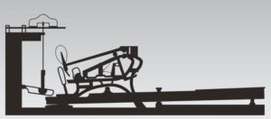
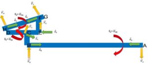
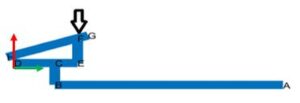
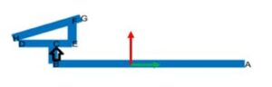
While making research for enhance the dynamic perspective for piano key mechanism at online, we came across an article which fulfills our goals. The article, “Modelling the dynamics of the piano action: is apparent success real?” by Anders Thorin, Xavier Boutillon and José Lozada provides massive information about the dynamic analysis of piano key mechanism with their advanced experiments, calculations and manufacture. Those information that they provided were precious but the work was too advanced for our use and also we wanted to analyze the dynamics of the mechanism with our own learnings from the course. The only thing we got from this article is the representation of mechanism. They simplified the main mechanism to three parts as you can see from Figure 8a. We decided that simplified mechanism is suitable for our purposes and decided to use a similar type of that representation for our dynamic calculations.
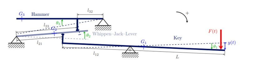
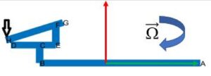
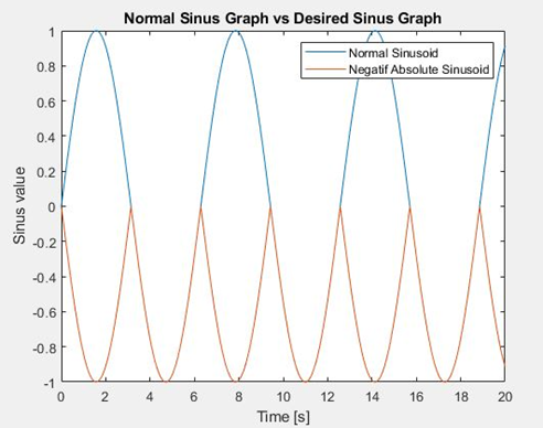
A sinusoid motion was a good choice but for key it was not appropriate. Key must start from horizontal position then must go down like the sinusoid curve’s negative part, but key must not go beyond from its’s initial horizontal position. To prevent that we took the absolute value of sinusoid curve then multiplied it by minus one to have an always negative sinus curve. As shown in Figure 9b now we have desired sinus graph with only negative values. Also, we had to divide our real life measured radian value by two because our sinusoid curve’s range dropped half after the modifications we mentioned before. After completing key’s angular displacement equation (q1) we wrote the other two parts’ angular displacement equations (q2, q3) with dependent to q1 with the ratios from Figure 8b.
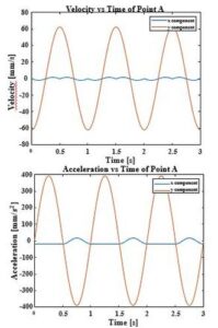
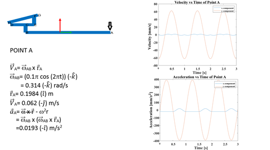
We did our dynamic calculations with using the equation we have learnt in class. In the calculations, we calculate the values at that instant when the key is hit. Since we have sine function for the displacement, the angular displacement and tangential acceleration becomes zero at that moment. That’s why we only have normal acceleration in the calculations as we always have in a rotation motion. We compare our calculations with MATLAB result that can be seen below as graphs and we see that they are fully correct. As we are going from point A to point H, the calculation become more complex and because of using limited decimals we have very small errors like %0.5. Also, we need to mention that points D and G are fixed.
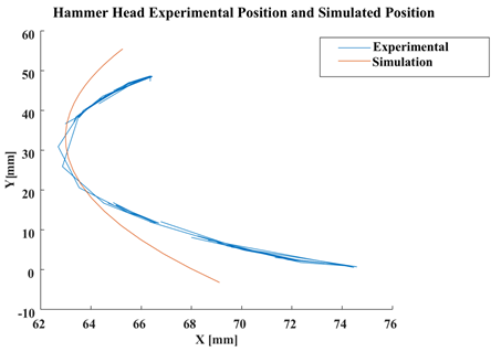
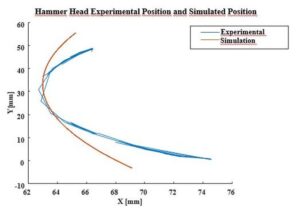
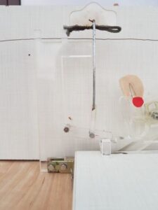
We did our experimental validation with using video tracking code in MATLAB. We record a video with putting a red piece of paper to the end of the hammer which corresponds to Point H in our simulation. We had some difficulties with validation as the hammer moves upward with a speed the red color became blur which is related with the quality of the camera and at some points, the data couldn’t be tracked. With increasing the range of the color, we had some successful hits which are enough to compare the positions of simulation and experimental results.