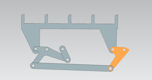
Box transport mechanism is a sporadic transfer mechanism for the industries where a process needs to be handled manually. This mechanism gives time to the operator to check the status of the product or any other procedures. The mechanism goes back to 1951 where the first patent for this type of box transfer system is issued.
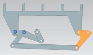
Box transport mechanism is a four-bar kinematic chain mechanism with a 1-degree of freedom. It works with only one actuator and this makes it a simple to work mechanism. Four-bar mechanisms are used thoroughly in the industry since they are very diverse and manipulative. They can translate a circular motion into any shape of motion by changing only the length of the linkages. The advantage of this system over regular conveyor systems is that in conveyor systems the delay can only be done by stopping the belt with various programs which is expensive.
Meet Our Team
MURAT SENTAY
DENIZ CAN COLAK
UTKU ULAS TEKIN
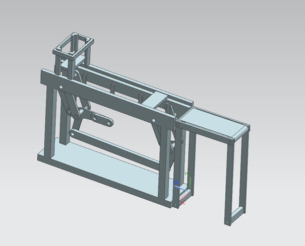
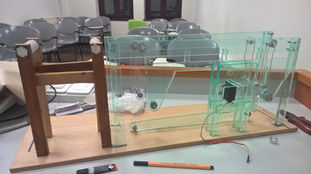
For the design of the mechanism we used the dimensions similar to other mechanisms, scaling the pieces for our project since we wanted a smaller mechanism. We used Siemens NX for the modelling of our design.
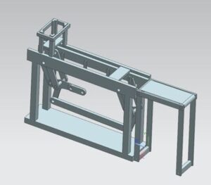
After the main mechanism of the moving parts are complete we proceeded to design a frame to support and hold our mechanism intact.
We also designed a conveyor belt at the end of our system.
The boxes will move along the side supports of the frame, after they reach the end they would drop on the conveyor belt and move continuously. After the assembly is complete we converted all the file formats for manufacturing them with the laser cutter.
Overall the design is composed of simple parts which were also easy to manufacture however the assembly and making design choices concerning the fit and scale of the pieces was challenging.
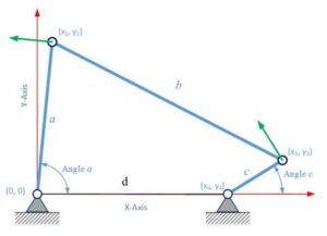
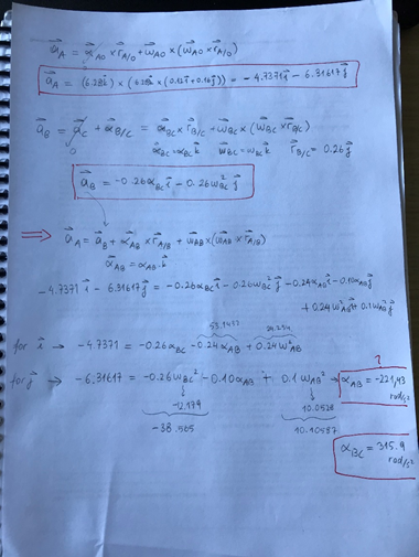
To determine the position, velocity and acceleration of the mechanisms we used the regular kinematic equations. To perform this task, first we needed to understand the four-bar mechanism. We solved a four-bar problem with kinematic equations with the relative motion equations.
MATLAB programming consisted of 3 different parts. The first one was finding the position, velocity and acceleration as a general form. For the first part we wrote the dimensions and our inputs and then wrote the equations we found.
Second part was simulation of the mechanism in MATLAB. This was a tricky part as we needed to write the code geometrically. We had to rewrite this code 3 times due to mistakes and misunderstanding of the mechanism. The main problem of the first codes were the elongation and shortening of the linkages. We needed to figure the angles correct before we could have fixed these problems. After solving these problems, we easily wrote a code that was simulating the motion of our mechanism.
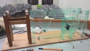
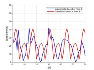
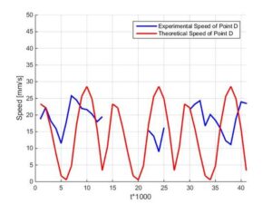
The third part was point tracking in video and getting the experimental values from the manufactured mechanism and comparing it with the theoretical values.
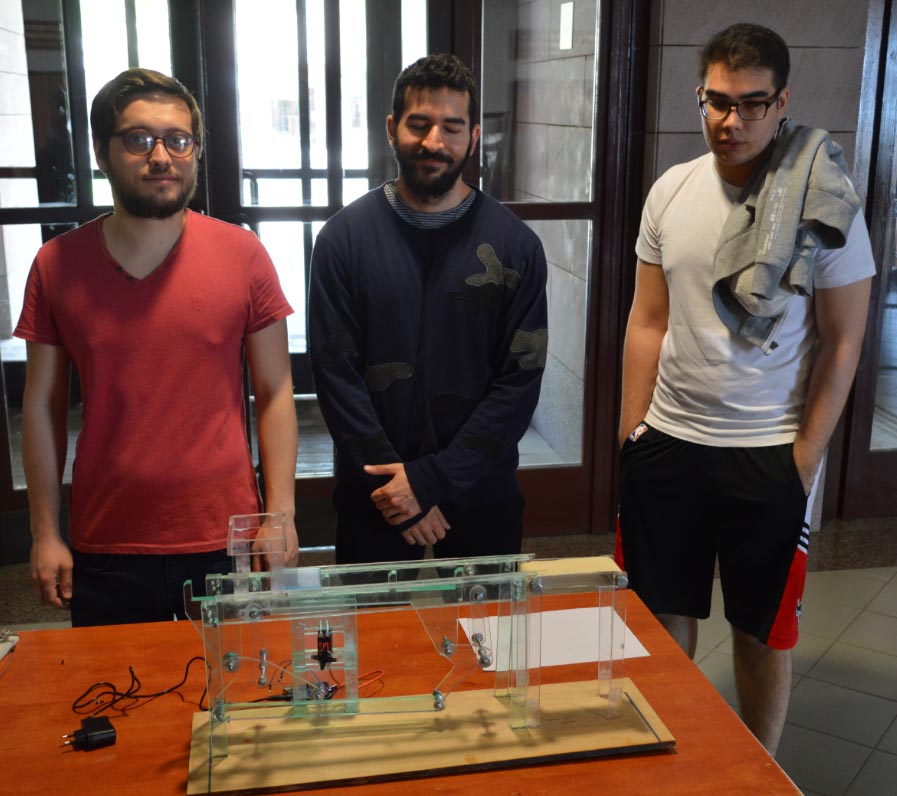
The first step in manufacturing was deciding on the material to use. Considering the spesifications and requirements of our system, we decided to use plexiglass (Poly (methyl methacrylate), (C5O2H8)n) for our mechanism. The reason for this choice was that plexiglass has really low density of 1.18 g/cm³, so it is very light which was good for our system in terms of reduced stress and friction. It was also a material that is easy to cut, drill holes on, and also costly beneficial compared to other materials. While working with it we have grown accustom to it and gained an understanding of the features of the material.
At the mechanical engineering workshop we couldn’t find a plexiglass sheet big and thick enough to cut the frame, so after some research we went to Sarıyer to acquire it. After getting the plexiglass sheet we proceeded to cut the parts from plexiglass with laser cutting machine at machine workshop. The tolerances for the laser cutter were less than milimeters which was fine for us, we didn’t had any problems with our parts in terms of faulty dimensions due to manufacturing.\
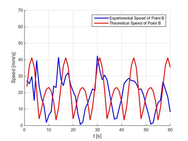
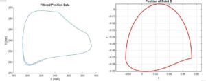
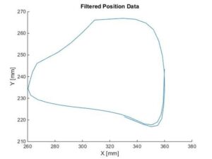
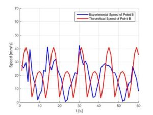
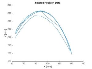
For experimental validation we chose two points. These two points were the most important points as they were the connector points between rigid bodies and transferring motion between them. After choosing these two points we filmed them with putting a red tape on each and tracked the motion. After that we combined the dynamics solution code and the video tracking code. We plotted the results on the same graph to see them clearly.