Our main goal in this experiment is to observe the circular motion, rotation about a rotating axis and the properties of the solar system through our mechanical model of the solar system, planetary orrery. Since planetary orrery is a simplistic imitation of the solar system which uses gear system, it also allows us to examine the working mechanism and utilization of the gears and their systems.
In addition, this experiment has some stages that requires the usage of some software such as MATLAB while gathering experimental and theoretical data, Siemens NX while designing the project, and Arduino while giving motion to the system. Therefore, this project also improves coding, and designing skills.
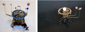
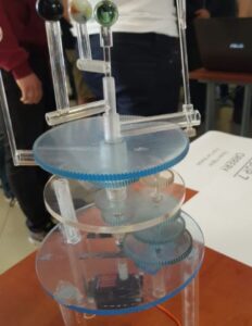
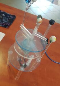
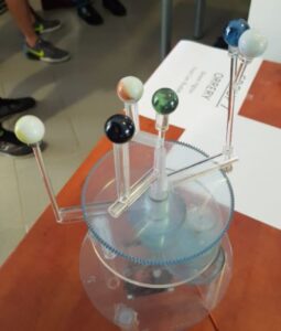
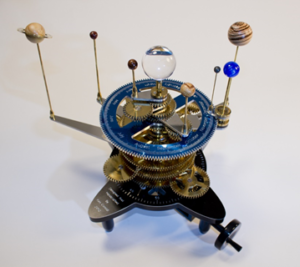
In this project orrery system is the mechanical model of the one part of solar system, first four planets, sun, and moon. The system is driven by clockwork mechanism simulates the circular motion of the planets around the sun and the circular motion of the moon around earth. The planets are not in appropriate scales and their turns around the sun is not elliptical since it is difficult to design or to construct the orrery system with elliptical trajectories and actual scales. Therefore, in this project the planetary orrery system is built by neglecting some of the properties of the solar system.
Meet Our Team
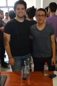
EKREM YIGITER
FIRAT CAN BUDAK
This project is about minimizing the solar system by making the rotations circular and downsizing the number of planets to 4 which are Mercury and Venus and Earth and Mars with Sun and Moon. In order to give life to this project we used gears for giving rotation to the planets and for transmitting the rotational energy.
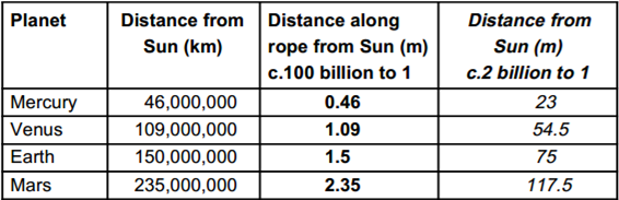
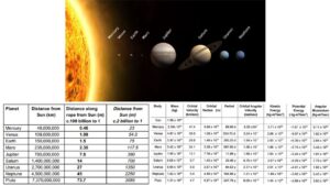
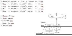
Because the size is minimized, the time needed to be minimized. Since the velocity of the planets which are in the minimized project can be changed, what matters for the design of the gears outside of the distances is the loop numbers that planets make while rotating around the world. If the Earth’s loop number is taken as the base and assuming Earth makes 100 tours, then the numbers come up as the followings:
-
- Mercury = 416 tours
- Venus = 164 tours
- Earth = 100 tours
- Moon = 1300tours
- Mars = 53 tours
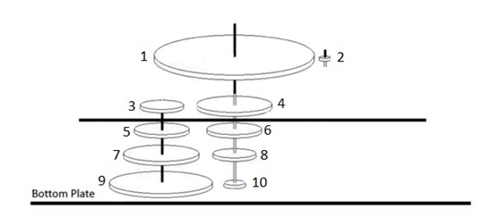
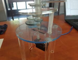
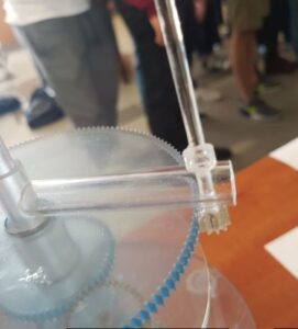
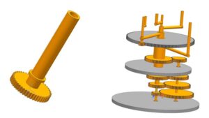
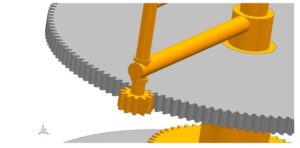
In the design 3-5-7-9 numbered gears are fixed to each other with the same pipe but not to bottom plane nor to the brace. 1-4-6-8-10 numbered gears are rotating independent from each other and have different pipes particularly. 10 numbered gear has the smallest pipe. After gear 10, gear 8 has the smallest pipe. The pipe sizes can be shown as 10 < 8 < 6 < Brace = 1 < 4.
All the pipes are fixed to their specific gears. Gear 1 and brace share the same pipe and do not move in order to give motion to the moon. Pipes that used for the freely rotating gears has bulge on them to keep the gears above from falling.
In the superposition points of brace and pipes and bottom plate, there are bearings that prevents the extra friction. But in the middle of the brace there are no bearings due to the mentioned case of moon above.
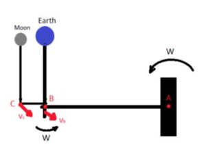
In our planetary orrery system planets make a rotation about a fixed axis, and the moon makes a rotation about a rotating axis since the moon rotates around the earth while the earth rotates around the sun.
In order to derivate the velocity and acceleration equations of the moon we need to be able to take the time derivative of a vector measured from the axis. In our case we can express our vector B in terms of its i, j, k components.
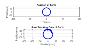
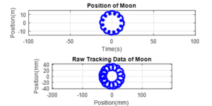
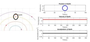
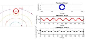
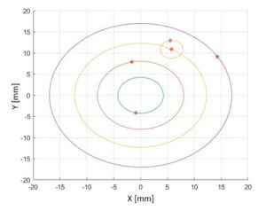
In the project it is crucial to make our calculations right to get the system running properly. In order to achieve that we need to check our experimental results by making the theoretical calculations and simulations. Therefore, we created the motion simulation of the planetary orrery system in MATLAB software. We used the circular motion equation to rotate the planets around the sun in their trajectories and in their actual distances to the sun.
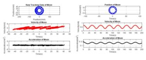
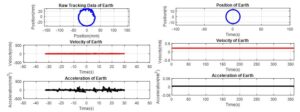
In addition, we used the MATLAB to get theoretical values for the project. From our simulation code we derived the theoretical position trajectory of the earth and moon. After that by taking the time derivative of the position code once and twice we get the velocity and acceleration data for the system, respectively. After that we graphed these data to compare with our experimental values. At the process of getting the experimental values from the system we record the video of the running orrery system. We used motion tracker to find the earth and moon’s position trajectories. After that by taking the time derivate of position we get the experimental velocity and acceleration data for earth and moon. Finally, we graphed our experimental data and compared it with the theoretical values to see how successful we are.
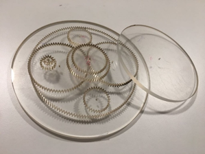
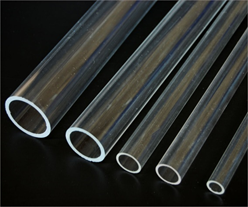
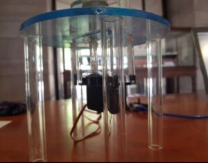
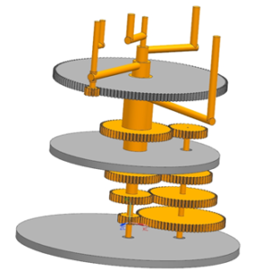
For this project, there was not a lot of option to proceed in manufacturing. One option is to make the whole project with steel, but it would be expensive for us to create. Another option was to use wooden gears, but the risk of losing the teeth of the gears while the system running eliminated the wooden gear option. Therefore, we decided to use plexiglass gears and pipes to manufacture the system since plexiglass is easier to access, more economic and more safer choice than the other options.