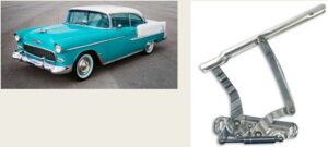
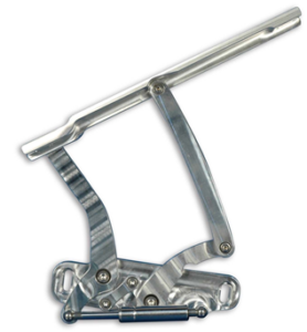
Our project was to design, manufacture and dynamically analyze the mechanism for a car’s hood hinge. We started out by searching possible model candidates from the internet. We would use the design as a template for our CAD. First, we implemented the design of a Chevrolet model. Model was the Monte Carlo from the year 1972.
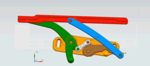
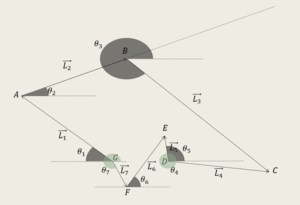
Then we used images of the hood hinge to design our CAD models. The mechanism we chose was a six-bar mechanism, which is used commonly throughout the automotive industry. So, we were sure that the mechanism was tested and approved by multiple companies. In the end that proved to be true and our design was working flawlessly. As explained earlier our mechanism is a six-bar mechanism with two fixed joints. This allows it to have only one degree of freedom. This means that the whole system’s motion can be constrained by each of the link’s definition. Also, the angles between the horizontal axis and each link can be written as expressions that have a single common variable. The CAD modeling was done using the program Siemens NX 11. Simulations in Siemens NX 11 showed that the mechanism would work in the real world without any interference between any of the parts in the mechanism.
Meet Our Team
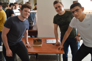
ALPER HAYRETTIN TUFAN
BILGEHAN BALI
BUGRAHAN BAHADIR
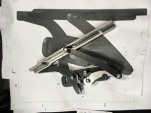
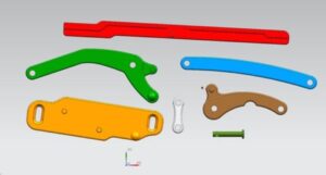
The step after choosing the mechanism for our project was to create a 3D working model of the mechanism in digital environment. In order to achieve this properly we used the dimensions from an already existing image of an aftermarket hood hinge for the make and model of the car we chose. Then we used a command in Siemens NX 11 called “Raster Image”, which plasters an image of the user’s choosing onto a specified plane for reference purposes. So, we used the image in the introduction part of this report. We drew each of the parts separately and assembled them in an assembly file.
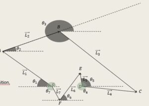
To dynamically analyze the mechanism, we had to create a mathematical model of our mechanism. For the mathematical model we used a geometrical approach in the beginning but that proved to be too prone to errors. Also, Prof. Lazoğlu informed the class that the geometrical approach was not acceptable for the course. So, we ditched the geometrical approach in favor of an analytical approach. We expressed each of the links as vectors and defined the horizontal and vertical components of these vectors using the lengths and the angles that they are pointing at with respect to the horizontal axis.
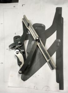
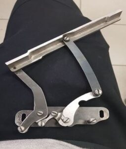
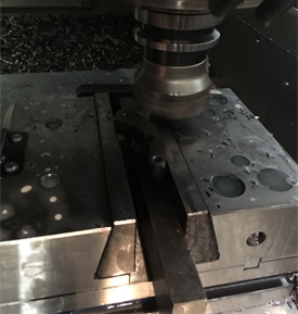
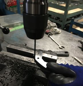
The manufacturing process was by far one of the most straightforward processes among the other tasks performed throughout the project. Even though the school provided assistance for this project, we decided it would be better for us to take care of this step outside of the school. That decision was made based on the tightness of the machine shop’s schedule and the limitations of material and equipment. We wanted to use some kind of metal whether it would be an alloy of steel or aluminum, because it keeps the model from becoming too ideal and pristine. In the end we used a thick sheet metal for our mechanism. Some parts were mostly two dimensional, so they were cut on the plasma cutter and then deburred but a few of the parts were more complex so they were milled on a CNC milling machine.
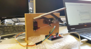
After manufacturing we discovered that the tolerances we gave for the holes were sufficient and the mechanism operated without binding. After that we screwed two pieces of Medium Density Fiberboard (MDF) together to make a simple base for our mechanism. Then we cut a small rectangle slightly larger than the servo motor we used at the right height. With all of the parts installed we bent a small piece of hardened steel wire taken from a broken umbrella to transfer the motion of the servo motor to the mechanism. With that the mechanism was ready for both the experimental validation and the demonstration.